Endotracheal tube with tip directional control and position preserving mechanism

A technology for endotracheal intubation and catheters, applied in the direction of endotracheal intubation, catheters, and medical devices

Inactive Publication Date: 2004-12-29
MERLYN ASSOCS
View PDF12 Cites 21 Cited by
  • Summary
  • Abstract
  • Description
  • Claims
  • Application Information

AI Technical Summary

Problems solved by technology

Although Heaven's patent includes a balloon at the end of the flexible s...

Method used


Image

  • Endotracheal tube with tip directional control and position preserving mechanism
  • Endotracheal tube with tip directional control and position preserving mechanism
  • Endotracheal tube with tip directional control and position preserving mechanism

Examples


Embodiment Construction

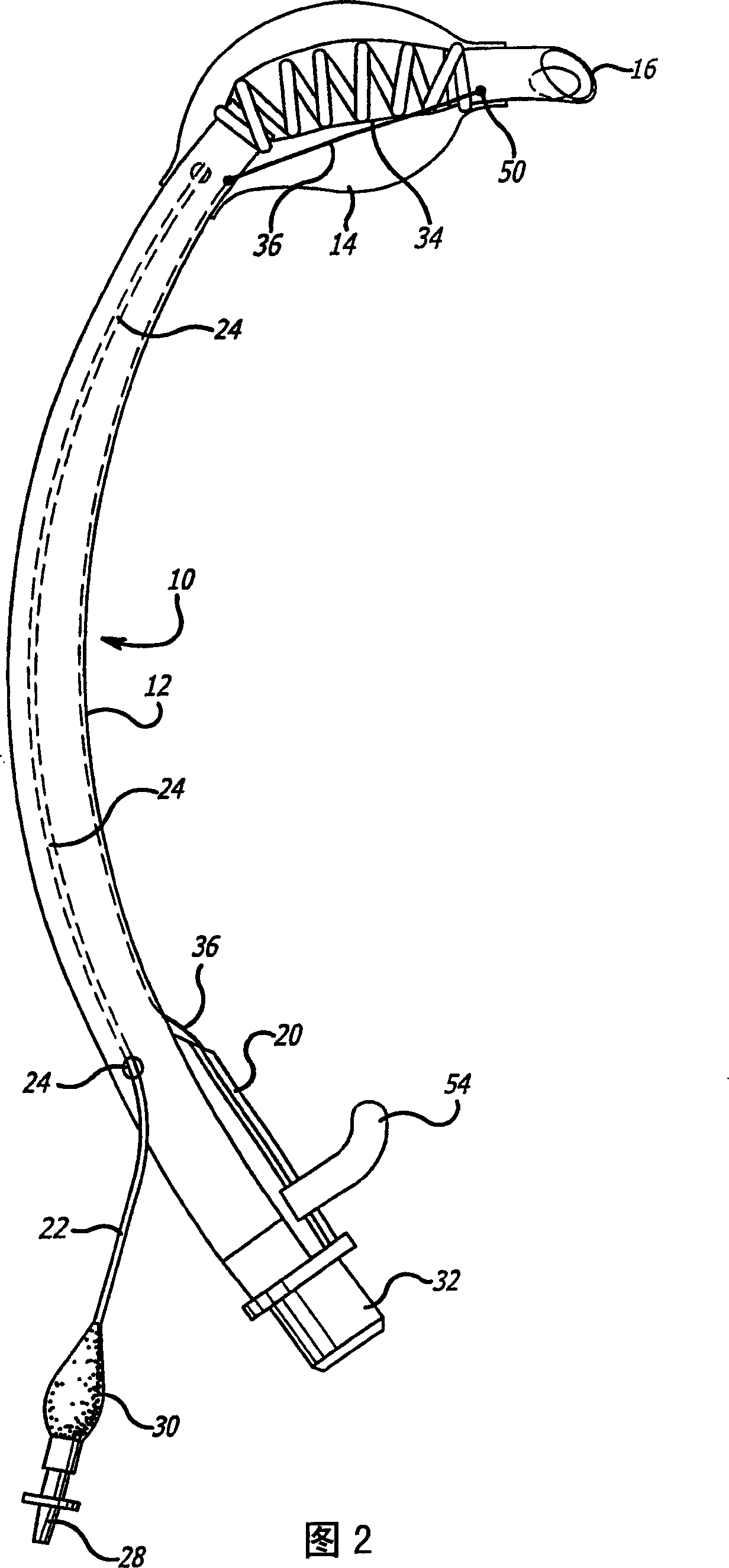
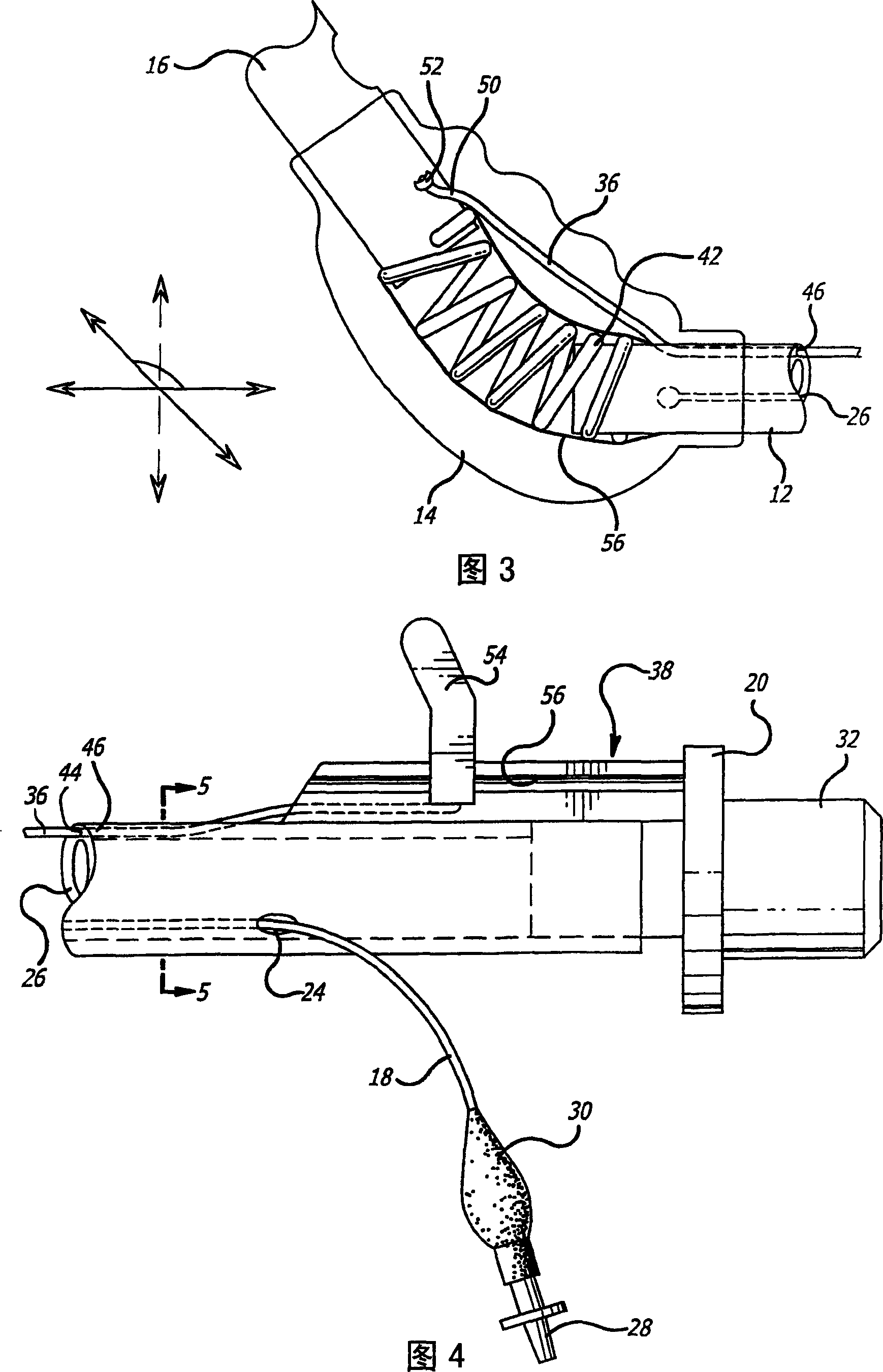
[0054] Figures 1 to 5 show a first embodiment of an endotracheal tube 10, alternatively referred to as an endotracheal tube, incorporating features of the present invention. The endotracheal tube 10 has a tubular body 12 with an inflatable balloon 14, which may also be referred to as a cuff, mounted to the outer surface of the tubular body 12 near the distal end 16 of the endotracheal tube. Conduit 18 is connected to the space between tubular body 12 and inflatable balloon 14, or to the inflated portion of a cuff in a multi-walled balloon. The catheter 18 extends from the proximal end 20 of the tubular body 12 to the distal end 16 of the tubular body 12 . Once tubular body 12 is positioned at its desired location in the patient's trachea, catheter 18 may be used to inflate balloon 14 to the desired occlusion diameter. Conduit 18 is typically a small diameter conduit 22 that passes through a passage 24 in wall 26 of tubular body 12 or extends along an inner or outer surface of...


PUM


Abstract

An endotracheal (10) tube which facilitates rapid intubation of the trachea, especially in situations where anatomical variation creates difficult intubating conditions, includes a portion that can be bent (34) during placement to control the position of the distal end (16) of the tube (10). The distal end (16) of the endotracheal tube (10) may be selectively curled or bent by a mechanism or fluid passage accessible from the proximal end (20) of the endotracheal tube (10). The endotracheal tube (10) provides for manipulation of the insertion end without occluding the lumen of the tube (10), to facilitate placement of the tube (10).

Description

technical field [0001] The present invention generally relates to an endotracheal tube. More specifically, the present invention relates to a device having a flexible portion designed to allow easy insertion of an airway tube (tracheal inlet) at places where it is difficult to insert due to anatomical changes, trauma, and the like. Endotracheal tube. Background technique [0002] Endotracheal tubes generally consist of a cylindrical tube that serves as a passage for gases to deliver oxygen and anesthetic gases directly to the patient. The cylindrical catheter terminates to form an open distal end to facilitate insertion of the catheter, and has an opposite open proximal end forming a connection to a gas source. A typical endotracheal tube has an inflatable cuff on the outside of the cylindrical tube for forming a seal with the outer wall of the tube. (See US Patent No. 3,460,541 to Doherty). A cuff is used to block the tube, which protects the windpipe and lungs from inh...

Claims


Application Information

Patent Timeline
IPC IPC(8): A61B1/00A61F11/00A61MA61M15/08A61M16/00A61M16/04A61M31/00
CPCA61M16/04A61M25/0133A61M2016/0418A61M16/0418A61M16/01A61M16/0434A61M16/0816
Inventor 安德鲁·J·托蒂迈克尔·H·王杰伊·科汀
Owner MERLYN ASSOCS
Why Eureka
Try Eureka