Remote control type analogue detecting instrument for instrument landing system of airplane

A technique for landing systems and aircraft instruments, applied in the field of remote analog detectors for aircraft instrument landing systems

Inactive Publication Date: 2005-01-05
JIANGXI HONGDU AVIATION IND GRP
View PDF0 Cites 3 Cited by
  • Summary
  • Abstract
  • Description
  • Claims
  • Application Information

AI Technical Summary

Problems solved by technology

But now there is a lack of an aircraft instrument landing system simulation tester s

Method used


Image

  • Remote control type analogue detecting instrument for instrument landing system of airplane
  • Remote control type analogue detecting instrument for instrument landing system of airplane
  • Remote control type analogue detecting instrument for instrument landing system of airplane

Examples


Embodiment Construction

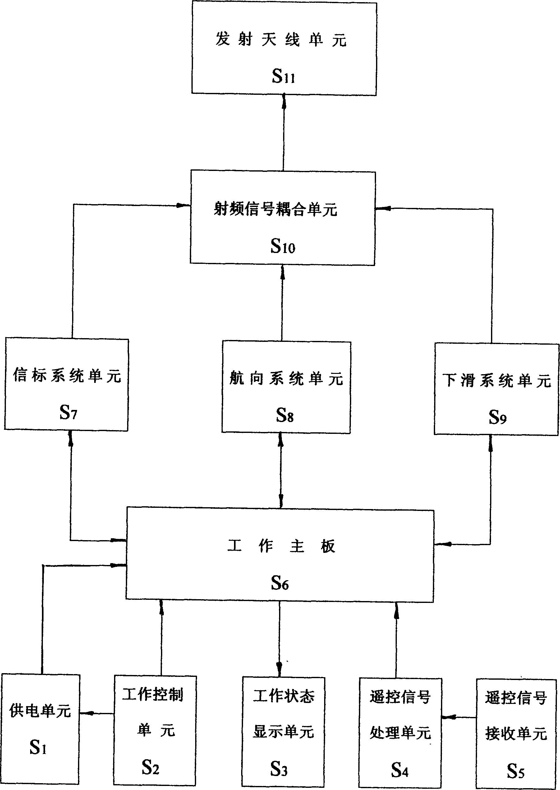
[0010] Such as figure 1 As shown, the present invention consists of a power supply unit S1, a work control unit S2, a total work state display unit S3, a remote control signal processing unit S4, a remote control signal receiving unit S5, a working main board S6, a beacon system unit S7, a heading system unit S8, and a sliding It consists of a system unit S9, a radio frequency signal coupling unit S10, and a transmitting antenna unit S11.

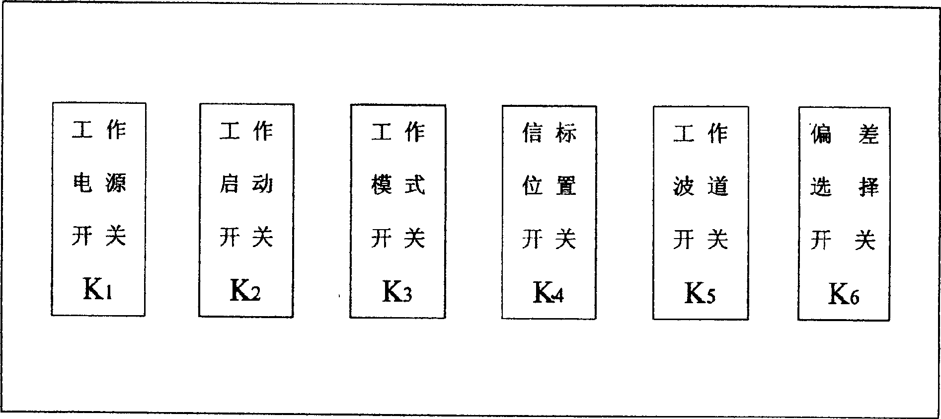
[0011] Such as figure 2 As shown, the working control unit S2 is composed of the working power switch K1, the working start switch K2, the working mode switch K3, the beacon position switch K4, the working channel switch K5, and the deviation switch K6. The remote control signal receiving unit S5 is connected to the remote control signal processing unit S4, the working control unit S2 is connected to the power supply unit S1, and the radio frequency signal coupling unit S10 is respectively connected to the beacon system unit S7, the headi...


PUM


Abstract

A remotely controlled simulative tester for the instrument landing system of airplane features that the working motherboard is connected to power supply unit, working unit, working state display unit, remote control signal processing unit, beacon system unit, direction system unit, and glide system unit, the RF signal coupling unit is connected to beacon system unit, course system unit, glide system unit and emitting antenna unit, the remote control signal receiving unit is connected to remote controll beacon processing unit, and the working control unit is connected to power supply unit.

Description

technical field [0001] The invention relates to a remote control analog detector for an aircraft instrument landing system. Background technique [0002] At present, for aircraft equipped with instrument landing systems at home and abroad, it is necessary to simulate the instrument landing system of the aircraft during assembly and commissioning and field maintenance to determine whether the system is normal. But at home and abroad all lack a kind of aircraft instrument landing system analog tester suitable for assembly commissioning and off-site maintenance to use now. Contents of the invention [0003] The purpose of the present invention is to design a remote-control type analog detector for aircraft instrument landing system, which is used for aircraft general assembly debugging and field maintenance. [0004] The present invention is realized in this way, it is made up of power supply unit S1, work control unit S2, work sta...

Claims


Application Information

Patent Timeline
IPC IPC(8): B64F5/60
Inventor 李国祥
Owner JIANGXI HONGDU AVIATION IND GRP
Why Eureka
Try Eureka