Pipe-cutting machine and cutting method

A cutting machine and pipe technology, applied in the direction of pipe shearing device, shearing device, shearing machine equipment, etc., can solve the problems of pipe mouth deformation, poor finish, unusable, etc., and achieve the effect of novel structure design and simple structure

Inactive Publication Date: 2005-01-12
HANGZHOU YOUCHENG PLASTIC STEEL PIPE
View PDF0 Cites 23 Cited by
  • Summary
  • Abstract
  • Description
  • Claims
  • Application Information

AI Technical Summary

Problems solved by technology

Disadvantages: First, the cut nozzle is deformed, and the finish is poor; second, it cannot be used in the pipe (plastic steel pipe) production line

Method used


Image

  • Pipe-cutting machine and cutting method
  • Pipe-cutting machine and cutting method
  • Pipe-cutting machine and cutting method

Examples


Embodiment 1

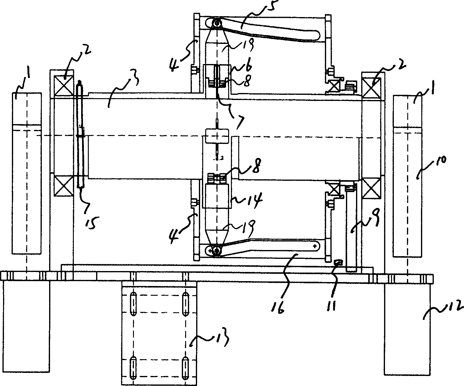
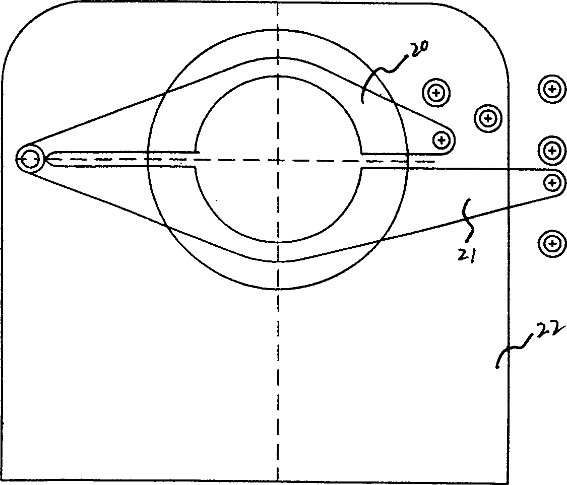
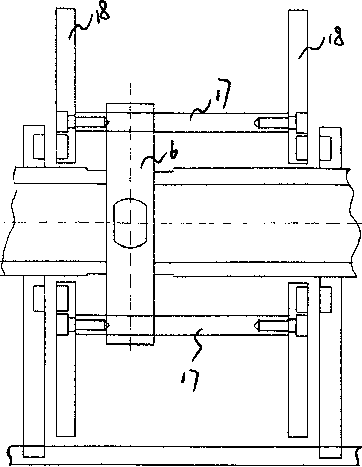
[0014] Embodiment 1: with reference to attached Figure 1~6 . Pipe cutting machine, the two ends of the main shaft 3 with threaded thread are positioned on the frame through the bearing 2, the main shaft 3 is a hollow main shaft, and threaded thread or part of threaded thread is formed on it. The opposite place between the main shaft 3 and the blade 7 has a blade inlet. The two clamping devices 1 are respectively located on the racks at both ends of the main shaft and driven by the cylinder 12 to clamp or loosen the clamping devices. The clamping device 1 is composed of an arc-shaped upper splint 17, an arc-shaped lower splint 18 and a bracket 19. One end of the upper clamping plate 17 and the arc-shaped lower clamping plate 18 are hinged and positioned on the support 19, the other end of the arc-shaped upper clamping plate is fixed on the frame, and the other end of the arc-shaped lower clamping plate is connected with the cylinder 12 through the connecting rod 10 (see attac...


PUM


Abstract

A pipe cutting machine is composed of machine frame, mainshaft positioned on machine frame via two bearings, two clamping units positioned at both ends of mainshaft on the machine frame, tool carrier-roller assemblage fixed to mainshaft, slide rod passing through said assemblage, the sliding rotary cage with guide disks connected to both ends of said slide rod, the driver unit consisting of motor, chain wheel and chain, stroke switch and electric control box.

Description

Technical field: [0001] The invention relates to a machine for cutting pipes, which belongs to the field of pipe cutting machine manufacturing. Background technique: [0002] Existing pipe pipe cutting machine, in structural design, motor drives emery wheel cutting piece. When cutting, put the pipe on the knife holder of the pipe cutting machine, turn on the motor, the motor drives the grinding wheel and press down to cut. Disadvantages: First, the cut nozzle is deformed, and the finish is poor; second, it cannot be used in the pipe (plastic steel pipe) production line. Invention content: [0003] Design purpose: To avoid the deficiencies in the background technology, to design a pipe cutting machine that can ensure that the pipe cut is not deformed, has a good finish, and can be matched with the pipe production line. [0004] Design scheme: 1. The main shaft is designed as a hollow shaft with threaded fasteners and a blade entry is provided on the hollow main shaft. Bot...

Claims


Application Information

Patent Timeline
Patent Type & Authority Applications(China)
IPC IPC(8): B23D21/04
Inventor 叶呈标
Owner HANGZHOU YOUCHENG PLASTIC STEEL PIPE
Why Eureka
Try Eureka