
Noise reducing device for vortex type compressor

A scroll compressor, noise technology, applied in the field of equipment to reduce the discharge noise of the scroll compressor

Inactive Publication Date: 2005-01-19
LG ELECTRONICS (TIANJIN) APPLIANCES CO LTD
View PDF0 Cites 5 Cited by
  • Summary
  • Abstract
  • Description
  • Claims
  • Application Information

AI Technical Summary

Problems solved by technology

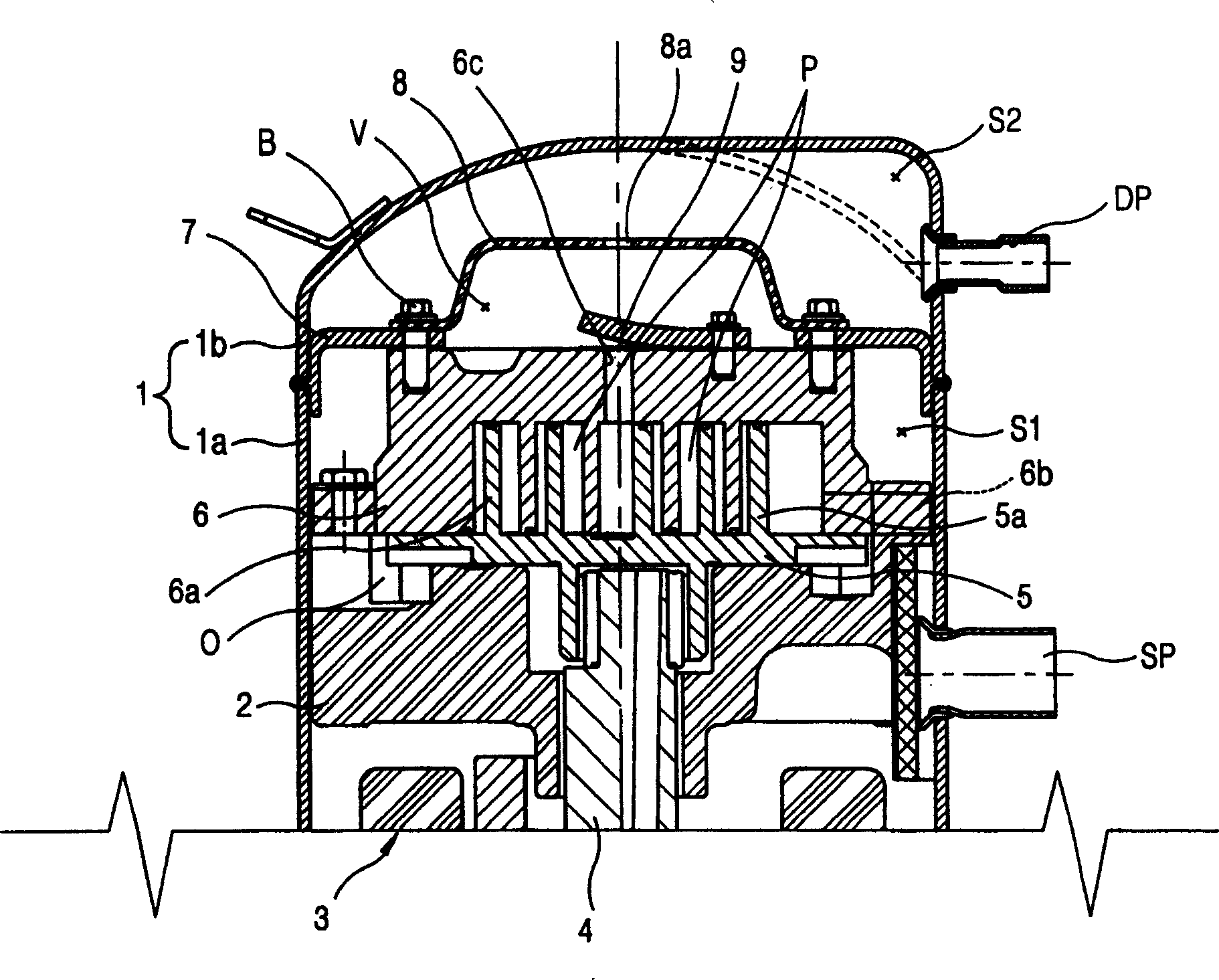
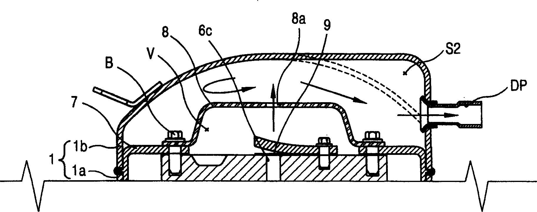
[0007] The purpose of the present invention is to solve the problems existing in the existing scroll compressor discharge noise device, and disclose a device that can provide a flow path for dispersing the discharge gas and reduce pulsating pressure, thereby reducing the discharge noise of the turbo compressor

Method used


Image

  • Noise reducing device for vortex type compressor
  • Noise reducing device for vortex type compressor
  • Noise reducing device for vortex type compressor

Examples


Embodiment Construction

[0025] The present invention is described in detail with reference to accompanying drawing as follows:

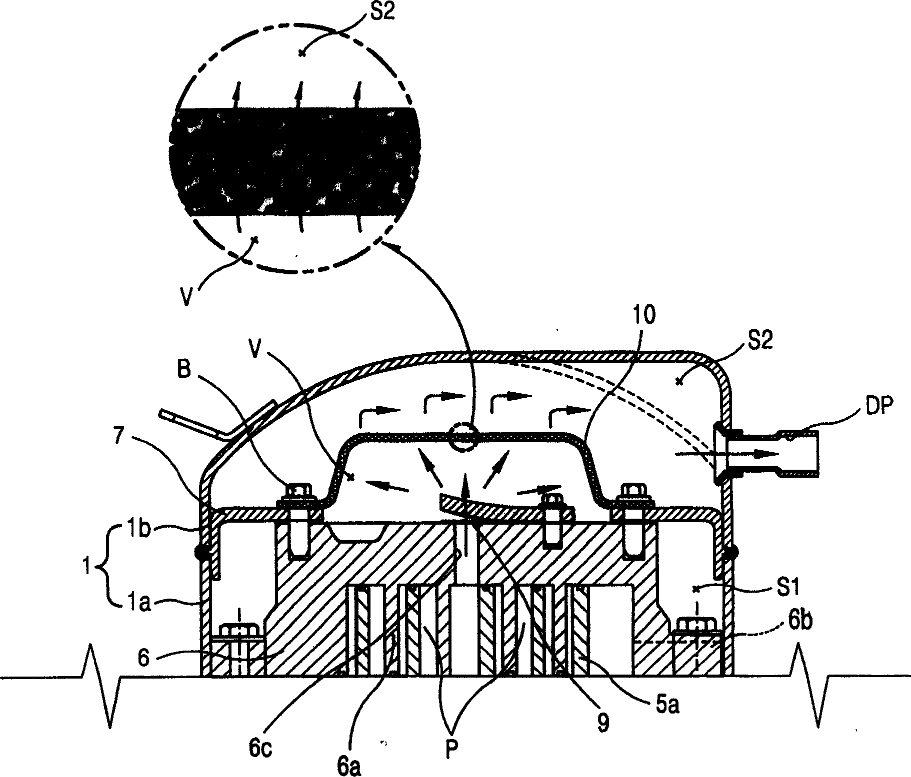
[0026] Such as figure 1 , 2 Shown in and 3, a kind of device that reduces the discharge noise of scroll compressor comprises: the sealed housing (1) of scroll compressor, is provided with gas suction pipe on the lower housing (1a) of sealed housing (1) (SP), the upper casing (1b) of the sealed casing (1) is provided with a gas discharge pipe (DP), and the main frame (2) and auxiliary frame (not shown) are respectively fixed on the sealed casing (1) The upper and lower sides of the interior; the drive motor (3) is installed between the main frame (2) and the auxiliary frame (not shown), and is pressed into the center of the rotor of the drive motor (3), thereby penetrating the main frame (2 ) of the drive shaft (4) of the drive motor (3); the movable scroll (5) is located on the main frame (2) and fixed together with the drive shaft (4), and the scroll (5a) of the movable ...


PUM


Abstract

The invention discloses a noise reducing device of scroll compressor, comprising a sealed casing, a static scroll disk fixed in the sealed casing, a dynamic scroll disk fixed on the driving shaft, an outlet cover fixed on the static scroll disk and forming an out let chamber, and a high-low pressure dividing plate which divides the sealed casing into suction area and outlet area. The invention is characterized in that: on the outlet cover, multiple small through holes are formed, the compressed gas from the compressing chamber can be outlet by the small through holes. In this way, the outlet path of the compressed gas is dispersed. The invention can reduce the pulsating pressure of the compressed gas, and consequently reduced the noise from the compressor.

Description

technical field [0001] The invention belongs to a device for reducing the discharge noise of a scroll compressor, in particular to a device for reducing the discharge noise of a scroll compressor with double support along the axial direction. Background technique [0002] Generally speaking, turbo compressors are widely used in the field of air conditioners. As high-efficiency and low-noise compressors, their operation method is to make two turbines rotate relative to each other, so that multiple pairs of turbines are formed. The compression chamber moves rapidly to the center, and at the same time, the volume becomes smaller, so that the refrigerant gas is continuously sucked in, compressed and discharged. Such as figure 1 , 2 Shown, the structure of existing scroll compressor is: the sealing shell (1) of turbo compressor, on the lower shell (1a) of sealing shell (1), be provided with gas suction pipe (SP), The upper casing (1b) of the sealed cas...

Claims


Application Information

Patent Timeline
Patent Type & Authority Applications(China)
IPC IPC(8): F04C18/02F04C29/06
Inventor 周永世
Owner LG ELECTRONICS (TIANJIN) APPLIANCES CO LTD
Learn More