Exhaust system with installation panel

a technology of installation panel and exhaust fan, which is applied in the direction of ventilation system, heating type, lighting and heating apparatus, etc., can solve the problems of difficult to get to the snap-on groove with precision, difficult to install and replace such panels, and many inconveniences, so as to facilitate easy installation and repair work, reduce noise of exhaust fan in operation, and facilitate the effect of replacement and repair work

Inactive Publication Date: 2008-12-04
HANWAY TECH
View PDF14 Cites 11 Cited by
  • Summary
  • Abstract
  • Description
  • Claims
  • Application Information

AI Technical Summary

Benefits of technology

[0011]1. Panel module adopts flexible connection fitting adaptive to all kinds of materials, thereby facilitating easy installment and repair work on panel module.
[0012]2. Volute adheres to the bottom of housing, between which sponge layer is inserted as buffer to reduce noise of exhaust fan in operation.
[0013]3. Capacitor is placed in capacitance box on the volute, forming an integral entity with motor module, thereby making it easier for replacement and repair work.
[0014]4. Two pieces of stopping flakes, using springs for repositioning, are placed at the exit of exhaust assembly, thereby reducing friction of air passage.

Problems solved by technology

At the present, the traditional ceiling pipeline exhaust fan in the market consists primarily of panel, housing, motor, fan wheel and other accessories, wherein the panel is usually fixed with V hanger inside housing with very shallow snap-on groove; such being the case, in the process of installing the hanger, one must attach panel to the end face of housing as close as possible, but since operator cannot see the position of the snap-on groove, it is very difficult to get to snap-on groove with precision; moreover, it is very likely that the hanger falls through motor module trough which is fixed on the side wall of housing, thereby making it hard for the panel to install to its precise position.
Further, the above installation method is mostly suitable only for light panels made of plastic or other light materials, and would be inapplicable to such panels as made of glass or ceramic materials; then one would have to use bolt to fasten panel and housing, hence much of the inconvenience to install and replace such panels.

Method used


Image

  • Exhaust system with installation panel
  • Exhaust system with installation panel
  • Exhaust system with installation panel

Examples


embodiment 1

Preferred Embodiment 1

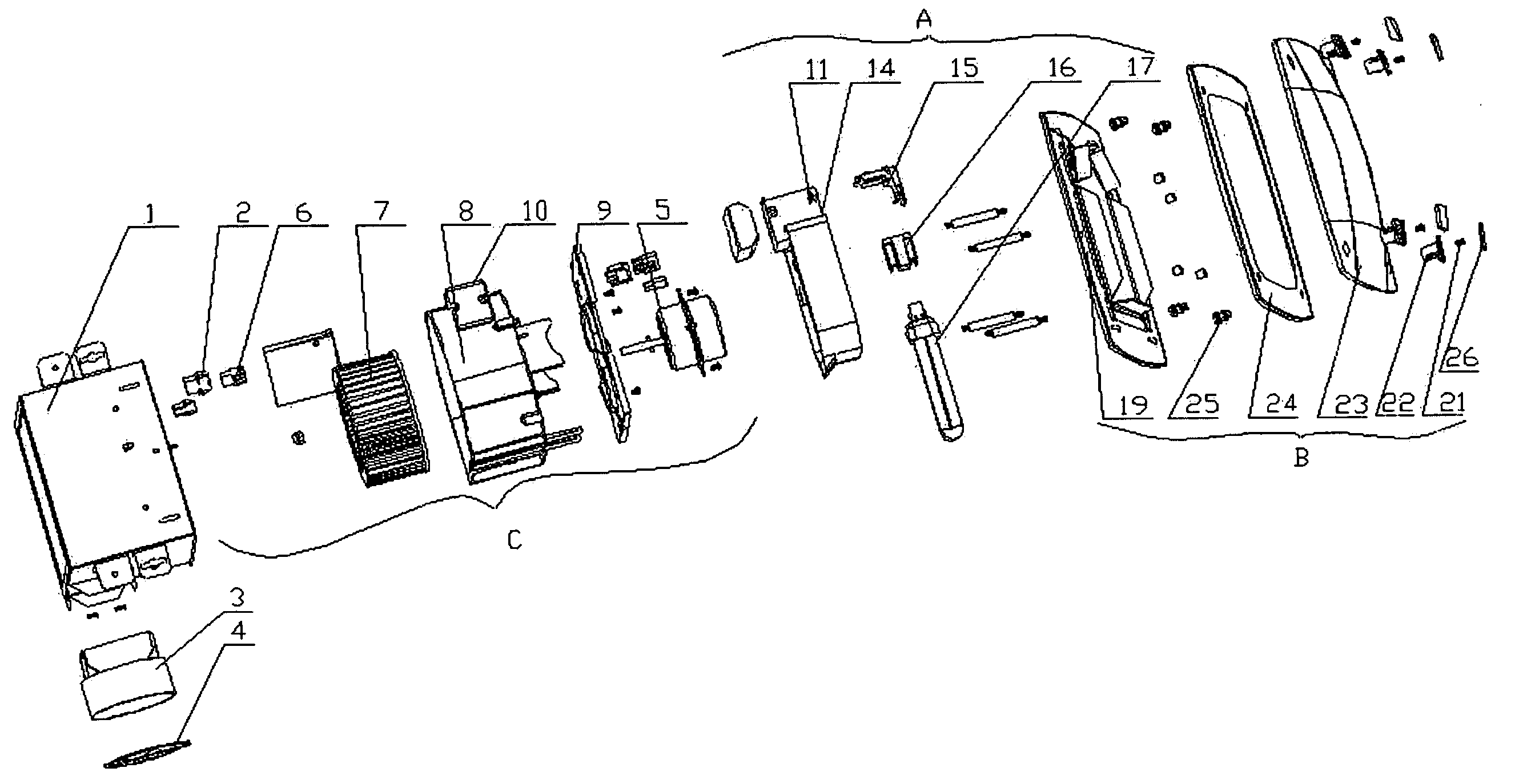
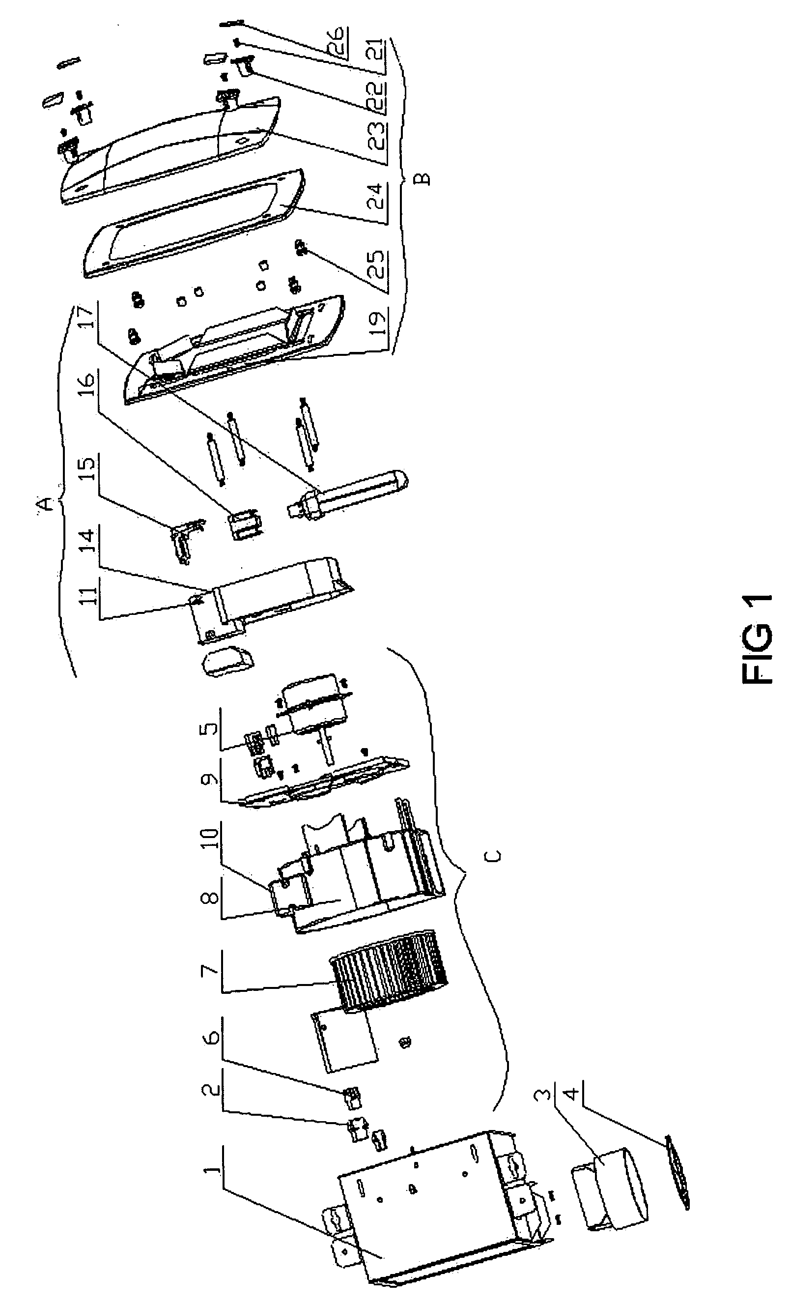
[0030]As shown in FIG. 1, the implemented pipeline exhaust fan includes housing 1 and the four following main parts placed on housing 1: panel module B placed on the end face of housing 1, motor module C placed in housing 1, light source module A placed between panel module B and motor module C, and exhaust assembly connected with vent-pipe and placed on outer side of housing 1.

[0031]As shown in FIG. 1 and FIGS. 5 through 8, this example indicates that panel module B of the exhaust fan consists of panel strut member 19, panel garnish member 24, panel main body 23, four panel connection members 25, bolt 21, bush 22 and garnish cover 26. Both panel garnish member 24 and panel strut member 19 are of hollow structure with frames. Panel strut member 19 uses bolts and nuts to connect with both housing 1 and motor module C to form one entity. Panel strut member 19 has four corners where keyholes 191 are made with slots and round apertures and aligned in identical dire...

embodiment 2

Preferred Embodiment 2

[0037]Preferred Embodiment 2 differs from Example 1 in flexible connection fitting of panel module B. Example 1 can apply to panels made of both light and heavier materials such as ceramics and glass, whereas Example 2 employs flexible connection fitting which applies primarily to panels made of light materials such as plastics. As shown in FIGS. 12 through 14, Example 2 indicates that panel module B includes panel 20 composed of panel frame and transparent plate, spring suppress piece 12, garter spring 18 and set screw. Garter spring 18 has two jaws 181 spreading outward in arc, whereas spring suppress piece 12 has one end exerted into round aperture of garter spring 18 to be fixed onto panel frame of panel 20 by set screw.

[0038]Upon volute 8 of motor module where lies garter spring 18, there is a mounting base 83 with two long grooves 84 that are symmetrically placed and perpendicular to the end face of volute 8; the installation of volute 8 should ensure the...


PUM


Abstract

A ventilating exhaust fan including a housing unit, a motor module, a panel module, and an exhaust assembly is provided. The exhaust assembly fixed on a side surface of the housing unit is improved by replacing single piece stopping flake with two-piece stopping flakes in order to reduce air flow friction, thereby overcoming the shortcoming of existing technique of stopping flake which, relying on gravity for reposition, gives rise to larger air flow friction. Furthermore, the noise of the existing pipeline exhaust fan is also reduced by adopting the methods of injection molding of motor module with volute as one entity, and by adhering to volute bottom sponge layer, which in turn is adhered to the base plate of exhaust fan housing.

Description

FIELD OF INVENTION[0001]The present invention relates to a ventilating exhaust fan and, in particular, a pipeline exhaust fan with replaceable panel.BACKGROUND OF THE INVENTION[0002]At the present, the traditional ceiling pipeline exhaust fan in the market consists primarily of panel, housing, motor, fan wheel and other accessories, wherein the panel is usually fixed with V hanger inside housing with very shallow snap-on groove; such being the case, in the process of installing the hanger, one must attach panel to the end face of housing as close as possible, but since operator cannot see the position of the snap-on groove, it is very difficult to get to snap-on groove with precision; moreover, it is very likely that the hanger falls through motor module trough which is fixed on the side wall of housing, thereby making it hard for the panel to install to its precise position. Further, the above installation method is mostly suitable only for light panels made of plastic or other lig...

Claims


Application Information

Patent Timeline
Patent Type & Authority Applications(United States)
IPC IPC(8): F24F7/06F21V33/00
CPCF21V19/04F21V33/0088F24F13/078
Inventor DENG, CHAOHUA
Owner HANWAY TECH
Why Eureka
Try Eureka