

Backlight module and light guiding board
A technology of backlight module and light guide plate, applied in optics, nonlinear optics, instruments, etc., can solve the problem of low brightness in the center of the light guide plate, and achieve the effect of good visual effect
- Summary
- Abstract
- Description
- Claims
- Application Information
AI Technical Summary
Problems solved by technology
Method used
Image

Examples
Embodiment Construction
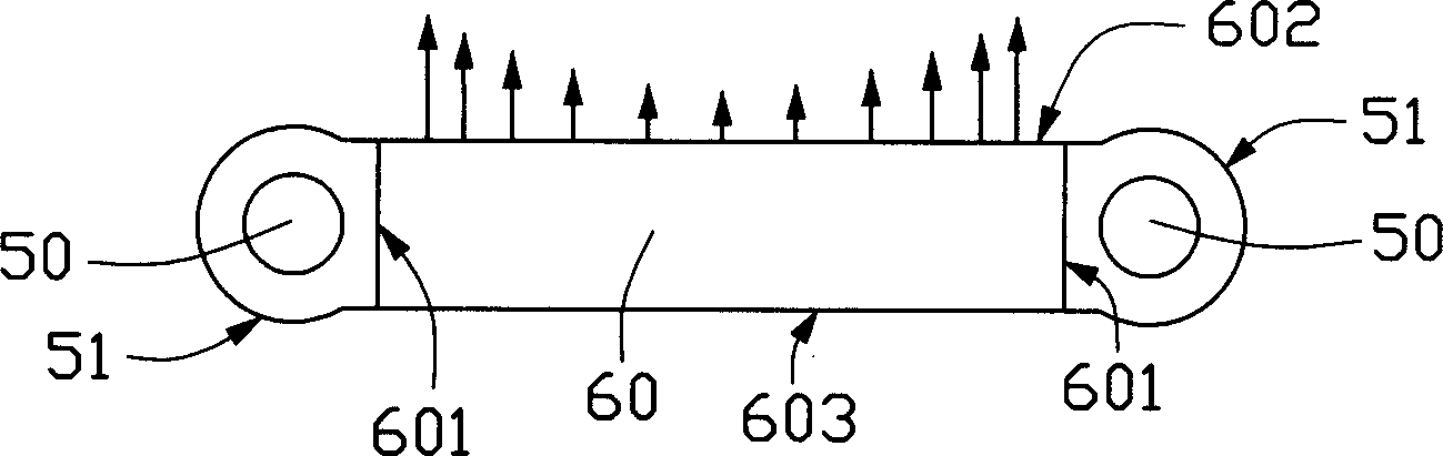
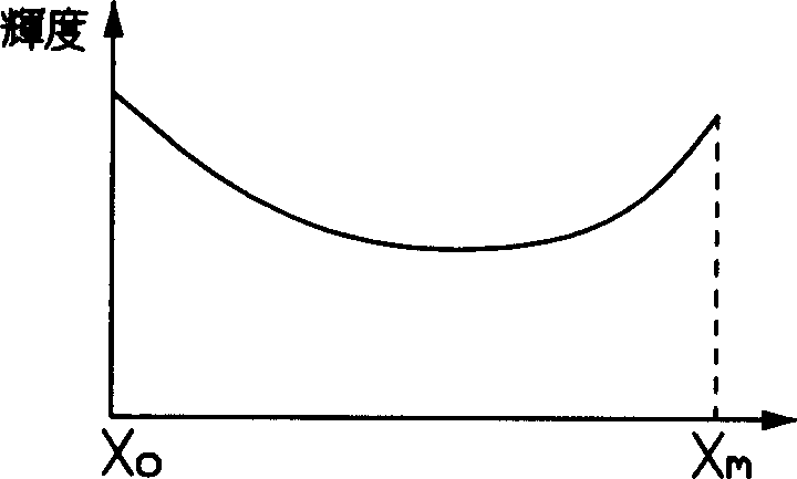
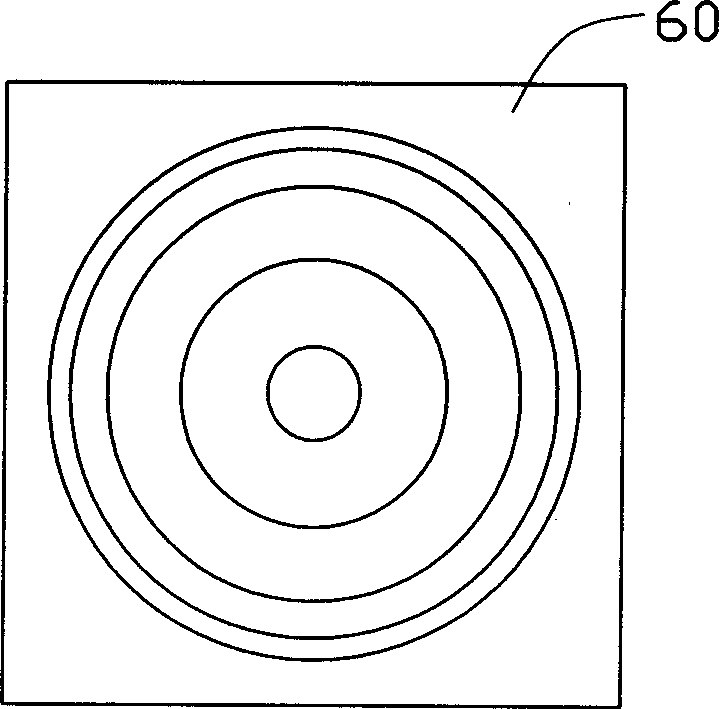
[0019] see Figure 4 and Figure 5 , is a structural schematic diagram of the backlight module of the present invention and a schematic diagram of the luminance distribution of the light guide plate. The backlight module includes a set of line light sources 10, a set of reflectors 11 arranged around the line light source 10, a light guide plate 20 and a light enhancement sheet 25, and the light guide plate 20 includes a light incident surface 201, a light exit surface 203 and a bottom surface 202 , the line light sources 10 are respectively located on the sides of the light incident surface 201 of the light guide plate 20 . The light emitted by the line light source 10 is transmitted in the light guide plate 20 , reflected multiple times between the light incident surface 201 and the bottom surface 202 , and finally exits from the light exit surface 203 and enters the brightness enhancement sheet 25 . The line light source 10 can be a CCFL (Cold Cathode Fluorescent Lamp, col...
PUM
 Abstract
Description
Claims
Application Information