

Elevator
A technology for elevators and cars, which is applied in the field of vibration-absorbing devices, and can solve problems such as increased structure and inability to accommodate
- Summary
- Abstract
- Description
- Claims
- Application Information
AI Technical Summary
Problems solved by technology
Method used
Image

Examples
Embodiment Construction
[0011] Embodiments of the present invention will be described below with reference to the drawings.
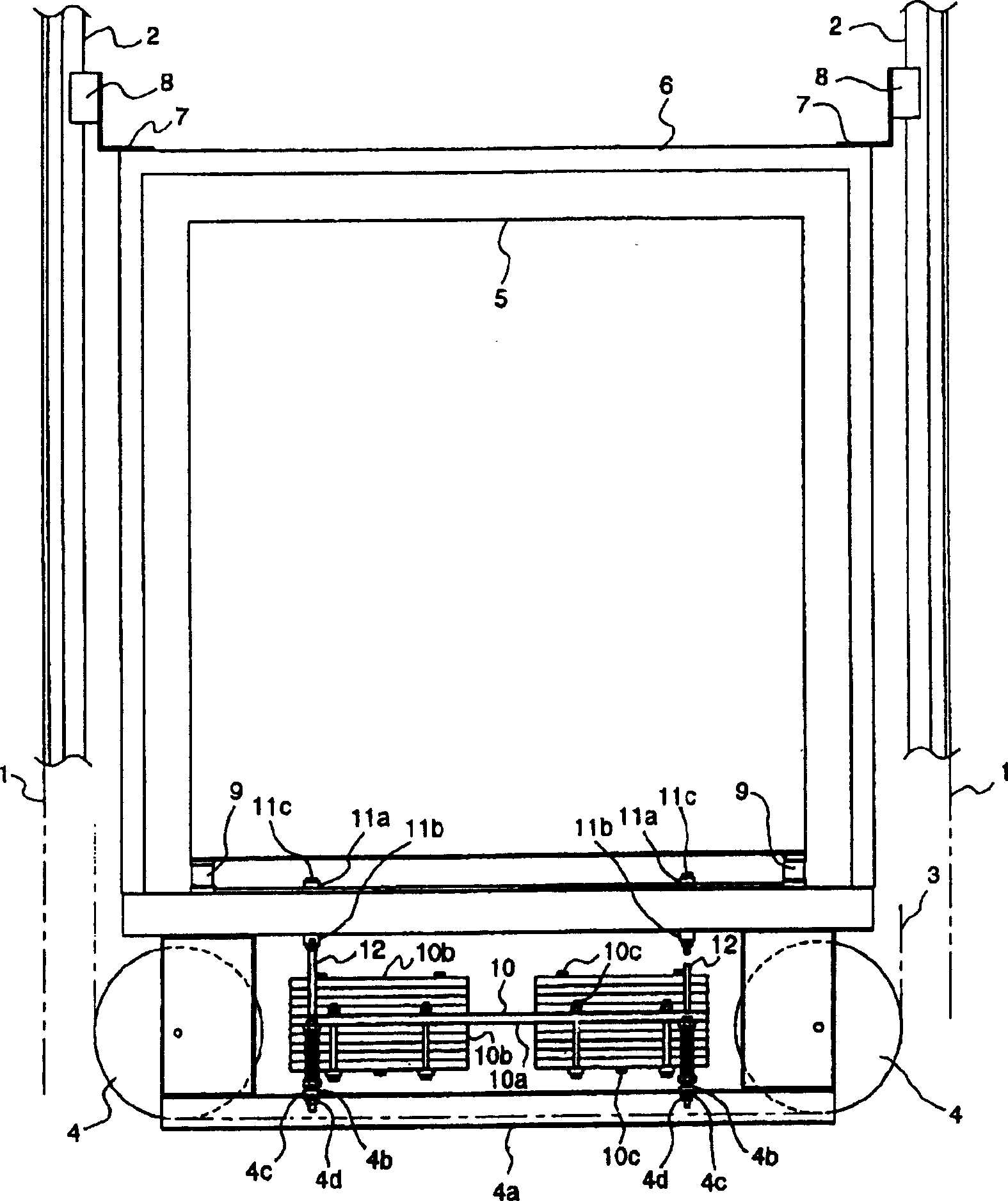
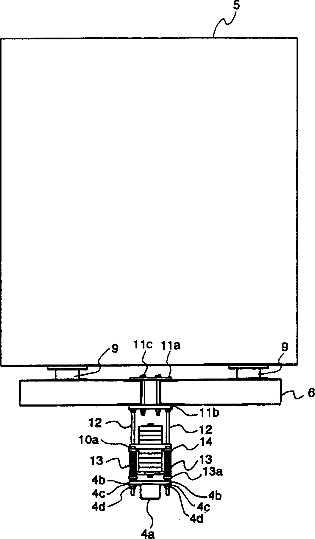
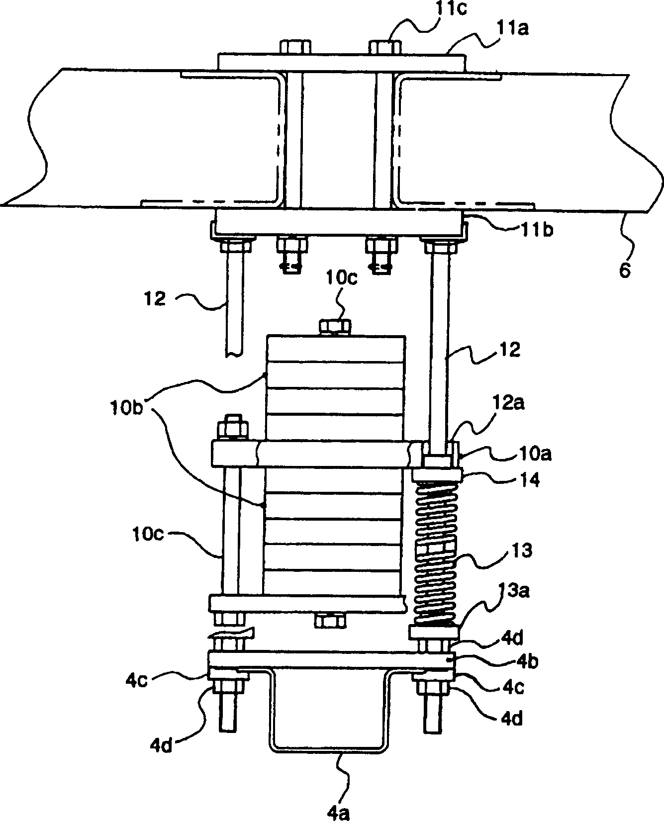
[0012] figure 1 It is a front view of a car frame part with an elevator vibration absorbing device according to one embodiment of the present invention. figure 2 yes figure 1 side view. image 3 yes figure 2 An enlarged view of the dynamic damper section of .
[0013] In the figure, 1 is the lifting channel of a high-rise building. Each guide rail 2 is vertically arranged on the two side walls of the lifting channel 1. Between the two guide rails 2, there is a lifter that passes through the lower pulley 4 of the car and is lifted freely. The cable 3 lifts the car frame 6 and the car 5 installed in the car frame 6 . In addition, each bracket 7 is attached to the upper and lower corners of the car frame body 6 (the lower part is not shown), and each guide device 8 is arranged in each bracket 7, which is arranged to be connected with each guide rail 2. The two sides and t...
PUM
 Abstract
Description
Claims
Application Information