
Non-rotating electrodeless discharge lamp system using circularly polarized microwaves

A circularly polarized wave and discharge lamp technology, applied in discharge lamps, circuits, electric light sources, etc., can solve the problems of limited dielectric constant, phase difference, troublesome and inconvenient production, etc.

Inactive Publication Date: 2005-02-02
美尔霓株式会社
View PDF3 Cites 8 Cited by
  • Summary
  • Abstract
  • Description
  • Claims
  • Application Information

AI Technical Summary

Problems solved by technology

[0005] However, the above technology, that is, artificially divides the above-mentioned electromagnetic waves into two components and guides them forcibly, and after the lengths of the above-mentioned waveguides are arranged in parallel, a phase difference occurs, the appearance of the discharge lamp becomes larger, and there are problems such as troublesome and inconvenient fabrication. When a dielectric is inserted into the hole, the electromagnetic field is separated into two directions, and a phase difference that causes the speed to differ occurs. The dielectric constant of the dielectric is limited, and there is a problem that the thickness of the mechanism becomes very large in order to achieve the desired level of the dielectric constant.

Method used


Image

  • Non-rotating electrodeless discharge lamp system using circularly polarized microwaves
  • Non-rotating electrodeless discharge lamp system using circularly polarized microwaves
  • Non-rotating electrodeless discharge lamp system using circularly polarized microwaves

Examples


Embodiment Construction

[0017] Hereinafter, the present invention will be described in detail with reference to the drawings.

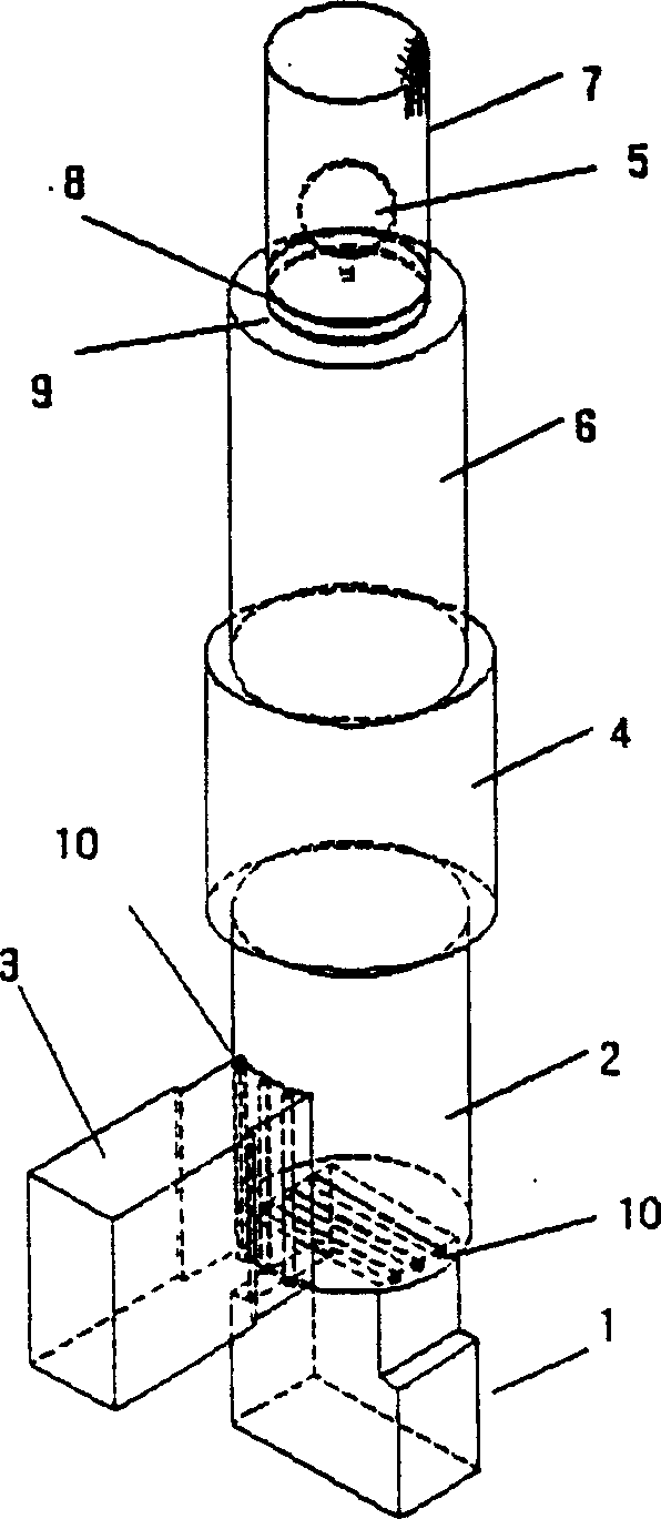
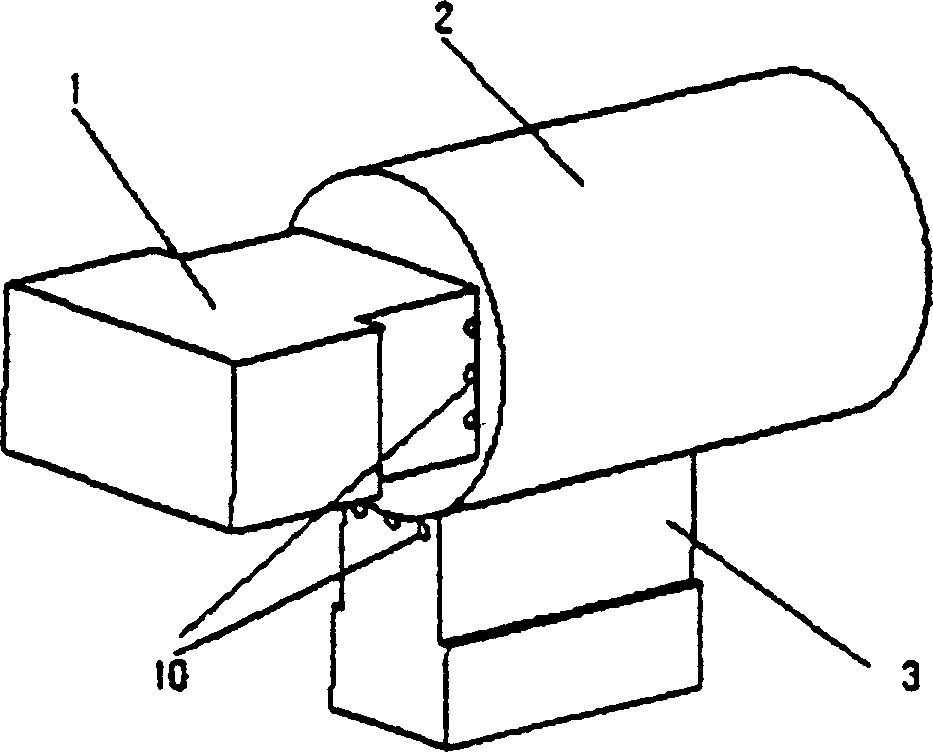
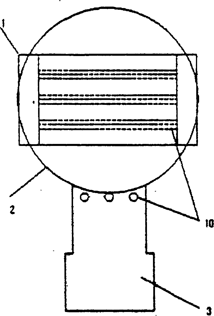
[0018] figure 1 is a schematic diagram of the non-rotating electrodeless discharge lamp system of the present invention using circularly polarized microwaves. refer to figure 1 , using a microwave oscillator to send out a linearly polarized wave microwave rectangular waveguide 1 and input cylindrical waveguide 2 are connected in a straight line, which can be used to obtain a circularly polarized wave balanced terminal closed rectangular waveguide 3 and input cylinder One side of the waveguide 2 is connected at right angles, the input cylindrical waveguide 2 and the elliptical waveguide (1 / 4 wavelength plate) 4 are connected in a straight line, and the elliptical waveguide 4 and the cylinder for installing the discharge lamp The waveguides 6 are connected in a straight line.

[0019] The mesh body 7 provided in sequence at the end of the above-mentioned cylindrical wavegui...


PUM


Abstract

Provided is a circularly polarized ultra-high-frequency generator that arranges an elliptic waveguide on the waveguide, where an electromagnetic field passes, by turning at a prescribed angle, and enables the electromagnetic field to arrive at a discharge lamp as circular polarized waves only by the minor axis and / or the major axis of the elliptic waveguide. In a circularly polarized wave converter for electrodeless discharge lamps, a rectangular waveguide that sends linearly polarized microwaves by using a microwave generator is connected with an input cylindrical waveguide straight, the rectangular waveguide, where termination is closed, is connected to the outer periphery surface of the input cylindrical waveguide at right angle, the elliptic waveguide is connected with the input elliptical waveguide straight so that the major axis is rotated at a prescribed angle for the horizontal plane of the input cylindrical waveguide, and a discharge lamp covered with a net body is connected with the cylindrical waveguide fixed on the plate of a reflector straight.

Description

technical field [0001] The present invention relates to a non-rotating electrodeless discharge lamp system using circularly polarized microwaves. Specifically, it relates to the following system, that is, on a waveguide passing through an electromagnetic field, the elliptical waveguide is rotated at a certain angle, and the waveguide is arranged using The inclination of the short and long axes of the elliptical waveguide allows the electromagnetic field to reach the discharge lamp as a circularly polarized wave. Background technique [0002] TE as the lowest fundamental mode in a cylindrical waveguide for general high-output electrodeless discharge lamps 11 Mode excitation, so the electric field of the microwave becomes a linearly polarized wave, but if a spherical lamp is inserted in the electric field of this linearly polarized wave and discharged, the plasma is in the form of TE 11 The mode discharge has an oval shape, and in the case of a high output discharge, local he...

Claims


Application Information

Patent Timeline
Patent Type & Authority Applications(China)
IPC IPC(8): F21S2/00F21Y101/00H01J65/04H01P1/16H01P1/17
CPCH01J65/044H01J65/04
Inventor 金振重金正愿吴炅变
Owner 美尔霓株式会社
Learn More