Arrangement for fixing wire harness onto covers of electric connection box and electric connection box thereof

A technology for electrical connection boxes and connection boxes, which is applied to structural parts of electrical equipment, electrical components, etc., can solve problems such as abnormal noise, wear and tear, and multi-assembly man-hours of vehicles, so as to prevent abnormal noise and wear of wiring harnesses, and improve distribution efficiency. Electrical reliability, the effect of preventing accidental falling off

Inactive Publication Date: 2005-02-02
YAZAKI CORP
View PDF0 Cites 6 Cited by
  • Summary
  • Abstract
  • Description
  • Claims
  • Application Information

AI Technical Summary

Problems solved by technology

[0007] In the above-mentioned existing structure, although the wire harness main line part 53 can be fixed in the connector cover 52, there is no device for fixing the wire harness branch line part 54, that is, the two wire harnesses or the two wire harnesses of the wire harness trunk line part 53 and the wire harness branch line part 54 are not fixed. The wire harness branch line part 54 is the device of the two wire harnesses. The wire harness branch line part 54 is unstable, and it is inevitable that there will be problems such as abnormal sound or wear and tear during the driving of the vehicle.
In addition, when the connector cover 52 is covered on the junction box main body 51, there is a problem that the harness branch line portion 54 is likely to be crushed.
In addition, when the harness branch line part 54 is thick (in the case of a large number of electric wires), the harness branch line part 54 expands in the connector cover 52, and the holding of the connector cover 52 and the connection box main body 51 is easy to be accidental. shedding problem
In addition, the fixing of the harness trunk portion 53 and the connector cover 52 requires complicated work such as wrapping tape or tightening a strap, and there is a problem that many assembly man-hours are required.

Method used


Image

  • Arrangement for fixing wire harness onto covers of electric connection box and electric connection box thereof
  • Arrangement for fixing wire harness onto covers of electric connection box and electric connection box thereof
  • Arrangement for fixing wire harness onto covers of electric connection box and electric connection box thereof

Examples


Embodiment Construction

[0038] Embodiments of the present invention will be described in detail below with reference to the drawings.

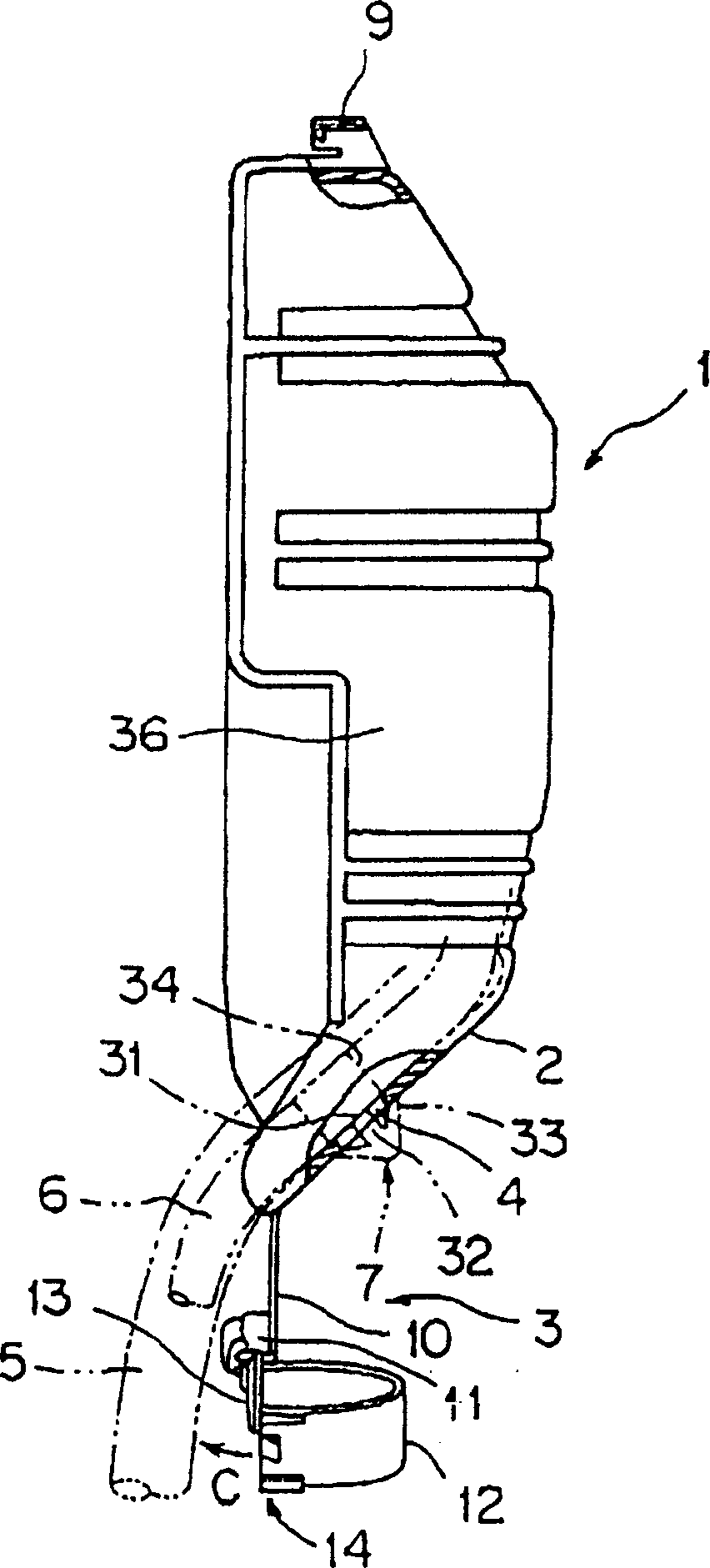
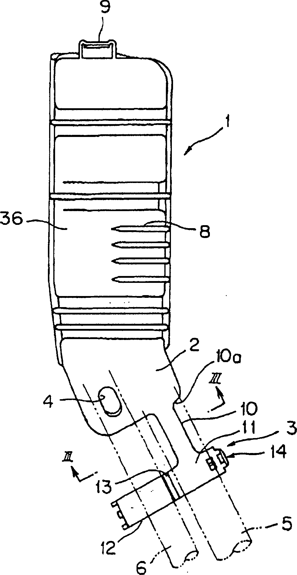
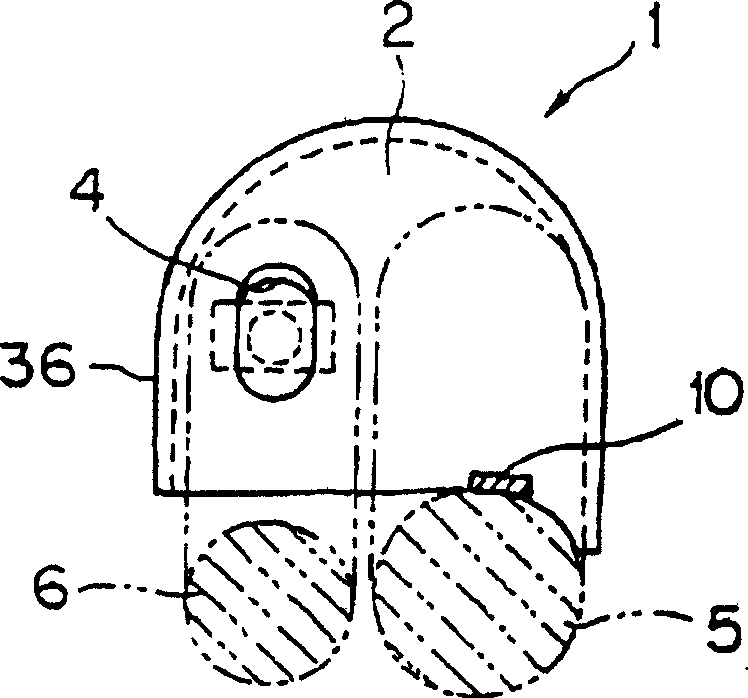
[0039] Each figure shows only the connector cover 1 made of synthetic resin, and omits the illustration of the main body of the electrical connection box on which electrical components such as relays and fuses, circuit boards, electronic components, and the like are mounted.

[0040] The connector cover 1 is approximately semicircular or approximately arc-shaped in section, and the middle part is formed in an approximately groove shape. Both ends in the longitudinal direction are inclined, and the height gradually decreases. Next to the inclined wall 2 on the side of one end, a wire harness is integrally provided. The holding part 3 is provided with a clip fitting hole 4 on the inclined wall 2 on one end side, and the thicker wire harness 5 is held by the wire harness holding part 3, and the holding clip 7 for fixing the thinner wire harness 6 fits into the clip fitti...


PUM


Abstract

The invention provides a cover arranged at the main body of an electrical connection box, which comprises a wall part for holding a first wiring harness and a second wiring harness connected with the electrical connection box. A first holding part is extended from the wall part in a derivative direction along the first wiring harness; the first wiring harness can be maintained outside of a holding component. The second wiring harness can be maintained at the wall part by a second holding part.

Description

technical field [0001] The present invention relates to a structure in which a wire harness drawn out from an electrical connection box is fixed to a cover attached to the electrical connection box, and an electrical connection box having the structure. Background technique [0002] Figure 7 ~ Figure 8 A mode of the wire harness fixing structure of the existing electrical junction box is shown (for example, refer to Japanese Utility Model Application Publication No. 63-109245 figure 1 , 2 ). [0003] This structure has a connector cover 52 covering the connector connection part of the electrical connection box, a groove-shaped fixing part 55 for fixing the wire harness trunk part 53 is provided on the connector cover 52, and a holding clip 56 is provided on the fixing part 55. The harness branch line part 54 drawn out from the connector 57 is covered with the connector cover 52 together with the connector 57, the harness main line part 53 is fixed to the fixed part 55 wi...

Claims


Application Information

Patent Timeline
Patent Type & Authority Applications(China)
IPC IPC(8): H05K7/00H02G3/16H02G3/20H02G3/30
Inventor 江川雅利关根由实杉浦智宏梅崎稔杉山嘉浩
Owner YAZAKI CORP
Why Eureka
Try Eureka