Movable grid at platform

A platform and fence technology, applied in the field of movable fences, can solve problems such as low cost

Inactive Publication Date: 2005-02-09
MITSUBISHI HEAVY IND LTD
View PDF2 Cites 3 Cited by
  • Summary
  • Abstract
  • Description
  • Claims
  • Application Information

AI Technical Summary

Problems solved by technology

but also req

Method used


Image

  • Movable grid at platform
  • Movable grid at platform
  • Movable grid at platform

Examples


Embodiment Construction

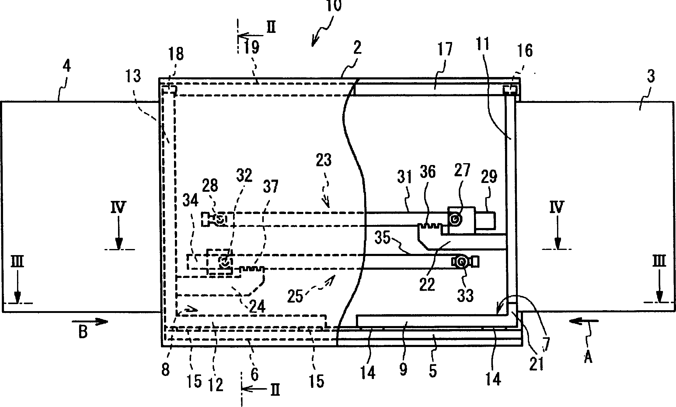
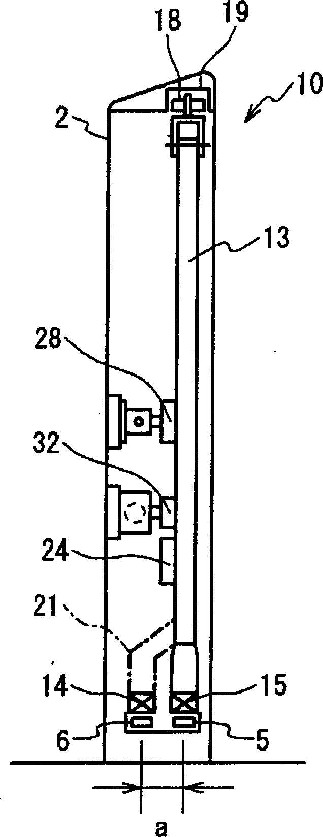
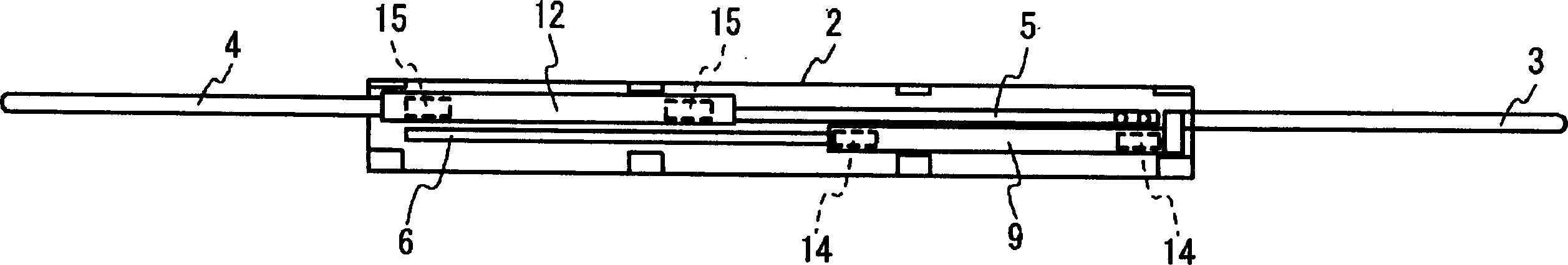
[0037] The movable fences on the platform of the present invention are arranged in pairs of two in the linear narrow area on the track side of the platform. The movable fence 10 is made of a single door bucket 2 and switch doors on the left and right sides. The opening and closing doors are composed of a first opening and closing door 3 and a second opening and closing door 4 . The first opening and closing door 3 and the second opening and closing door 4 can reciprocate in opposite directions. Here, the movement direction is seen as the left and right direction from the people standing on the platform, which is consistent with the track direction. The first opening and closing door 3 passes through the vertically long opening on one side (right side) of the door bucket 2, and the second opening and closing door 4 passes through the vertically long opening on the other side (left side) of the door bucket 2.

[0038] In the door bucket 2 , a pair of lower linear guide rails i...


PUM


Abstract

A first opening/closing door 3 and a second opening/closing door 4 are moved to a direction opposite to each other. A first horizontal support 9 supporting the first opening/closing door 3, arranged at a lower side of a shutter box 2 and extending in a first direction and a first guide rail 5 supported by the shutter box 2 and supporting the first opening/closing door 3 are arranged. The first opening/closing door 3 is supported at a first rear position positioned at a rear side in a storage direction of the first direction A of a first horizontal support 9. The first horizontal support 9 is unrotatably supported to the first guide rail 5 in a vertical plane. Rotation force by rotation moment caused by the first opening/closing door having a large mass is sufficiently supported. Both side opening/closing doors 3, 4 are stored in a narrow space of the shutter box 2 without being superposed and are stably supported by an unrotatable mechanism. In the state, the length of the installation space is shortened to the minimum.

Description

technical field [0001] The present invention relates to a movable fence on a platform, and particularly relates to a movable fence on a platform that adapts to the interval of doors on the vehicle side and shortens the door bucket. Background technique [0002] Passengers get on and off trains such as trams on platforms formed at stations. It is generally worried about accidents caused by people on the platform contacting the car body when the train departs and arrives, or accidents where people are involved due to the wind pressure of the train. In order to avoid such accidents, as can be seen in Patent Publication 1 shown later, there is known a safety measure technology in which a movable fence is provided on a platform. As a movable fence, a horizontal direction movable fence and a vertical direction movable fence are known. In order to move the movable fence in the vertical direction, the movable equipment is required to have a sufficient height in the vertical direct...

Claims


Application Information

Patent Timeline
IPC IPC(8): E01F1/00B61B1/02B61K13/04
Inventor 桥本芳丈浅野间俊朗岩本贤二仓田章彦
Owner MITSUBISHI HEAVY IND LTD
Why Eureka
Try Eureka