Bearing assembly with brazing or soft soldering connecting part

A technology for bearing assemblies and connecting parts, which is applied in bearing assembly, bearing components, rolling contact bearings, etc., can solve the problems of high carbon steel welding cracks, welding slag splashing, etc.

Inactive Publication Date: 2005-02-09
AB SKF
View PDF0 Cites 5 Cited by
  • Summary
  • Abstract
  • Description
  • Claims
  • Application Information

AI Technical Summary

Problems solved by technology

However, this can lead to weld slag spatter in the bearing space, in addition, welding of high carbon steel can cause severe cracking

Method used


Image

  • Bearing assembly with brazing or soft soldering connecting part
  • Bearing assembly with brazing or soft soldering connecting part
  • Bearing assembly with brazing or soft soldering connecting part

Examples


Embodiment Construction

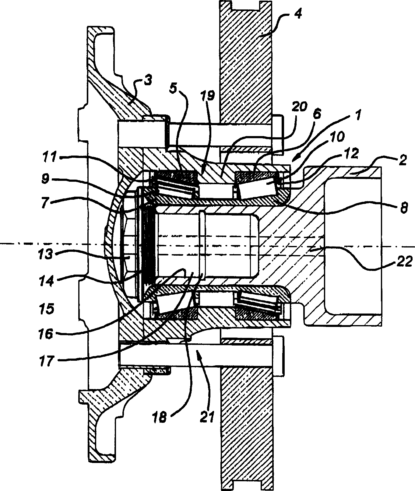
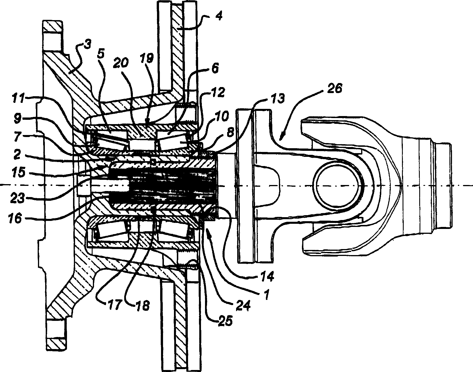
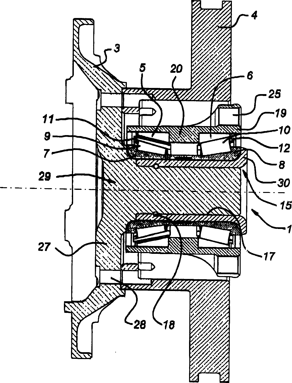
[0048] figure 1 The truck hub assembly shown in includes a bearing assembly 1 according to the invention attached to a steel hub element 2 fixed to the wheel suspension (not shown). A wheel rim 3 and a brake disc 4 are mounted on the bearing assembly 1 . The hub element 2 may comprise a tube end, which may have any cross-sectional shape, such as circular, square, triangular, conical, pyramidal, etc.

[0049] The bearing assembly 1 is of the double row tapered roller type with two outer retainers 5,6 and two inner retainers 7,8. A set of tapered rollers 9 and 10 are accommodated between the retaining rings 5, 7 and 6, 8, respectively, and these tapered rollers are held in a known manner by cages 11, 12, respectively.

[0050] In order to achieve proper performance of the bearing assembly 1, a certain axial preload should be applied to the tapered roller bearing. The preload is applied to the inner retainers 7 , 8 by means of nuts 13 which are screwed onto the threads 14 of t...


PUM

PropertyMeasurementUnit
melting pointaaaaaaaaaa

Abstract

The unit has an outer bearing ring (1) and an inner bearing ring (2) set concentrically and movable relative to each other. At least one of the bearing ring comprises two metal components (9,10) coupled side-by-side by a connecting unit (11). The connecting unit includes brazed and/or soldered connections (14,15) and a welded connection (16).

Description

technical field [0001] The invention relates to a bearing assembly comprising: at least two bearing parts, the bearing surfaces of which are movably supported on each other; and an auxiliary element connected to one of said bearing parts. Background technique [0002] Such bearing assemblies are well known in various fields. As an example, reference may be made to a truck hub bearing assembly comprising such a bearing assembly. One of the retainer components of the bearing is usually attached to the hub, which is attached to the axle of the truck or trailer. The bearings are held in place by nuts threaded onto the external threads of the hub. [0003] The connection between the bearing and the hub is subject to various loads and is therefore prone to fatigue degradation. Therefore, advanced materials such as high-grade steel must be used in this area to obtain acceptable fatigue life. However, this poses extremely severe restrictions on the choice of materials. For exam...

Claims


Application Information

Patent Timeline
Patent Type & Authority Applications(China)
IPC IPC(8): B23K1/00B23K1/008B60B27/00F16C19/38F16C33/60F16C33/64F16C35/06F16C41/00
CPCB23K1/0008F16C33/64F16C35/077F16C41/00B23K1/008B60B27/00F16C19/386B60B35/121F16C35/06F16C19/364F16C19/52F16C19/543F16C2226/34F16C2300/02F16C2326/02
Inventor 亨德里克斯·扬·卡帕恩约翰内斯·弗朗西斯库斯·范德桑登伊曼纽尔·雅克·埃罗科尔内留斯·彼得鲁斯·安东尼厄斯·菲瑟斯雅各布斯·兹瓦斯
Owner AB SKF
Why Eureka
Try Eureka