Automatized material conveying system and its storage cabinet

A technology for handling systems and storage cabinets, applied in the field of automated storage systems, can solve problems such as reducing machine setup rate and occupying area, and achieve the effects of simplifying design, saving space utilization, and reducing costs

Inactive Publication Date: 2005-02-16
AU OPTRONICS CORP
View PDF0 Cites 20 Cited by
  • Summary
  • Abstract
  • Description
  • Claims
  • Application Information

AI Technical Summary

Problems solved by technology

If a supporting structure is set up from the ground to support the crane track 142, it will occupy an area and reduce the installation rate of the machine

Method used


Image

  • Automatized material conveying system and its storage cabinet
  • Automatized material conveying system and its storage cabinet
  • Automatized material conveying system and its storage cabinet

Examples


Embodiment Construction

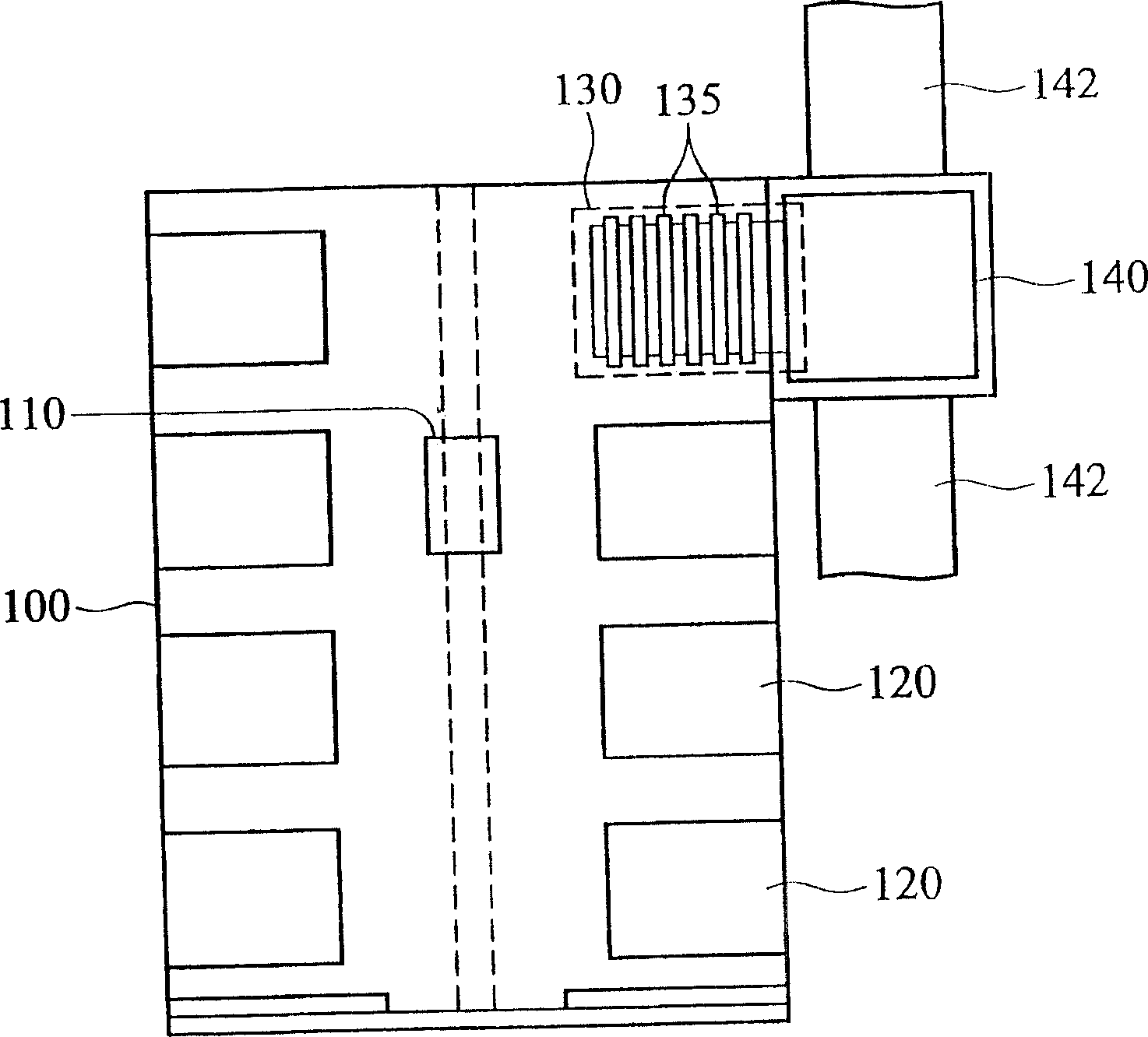
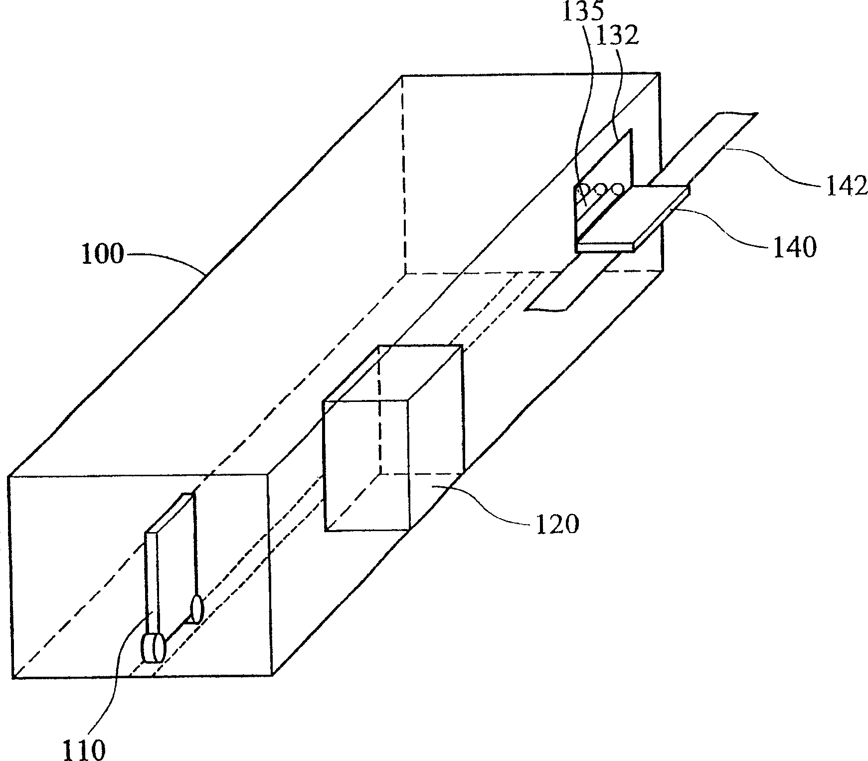
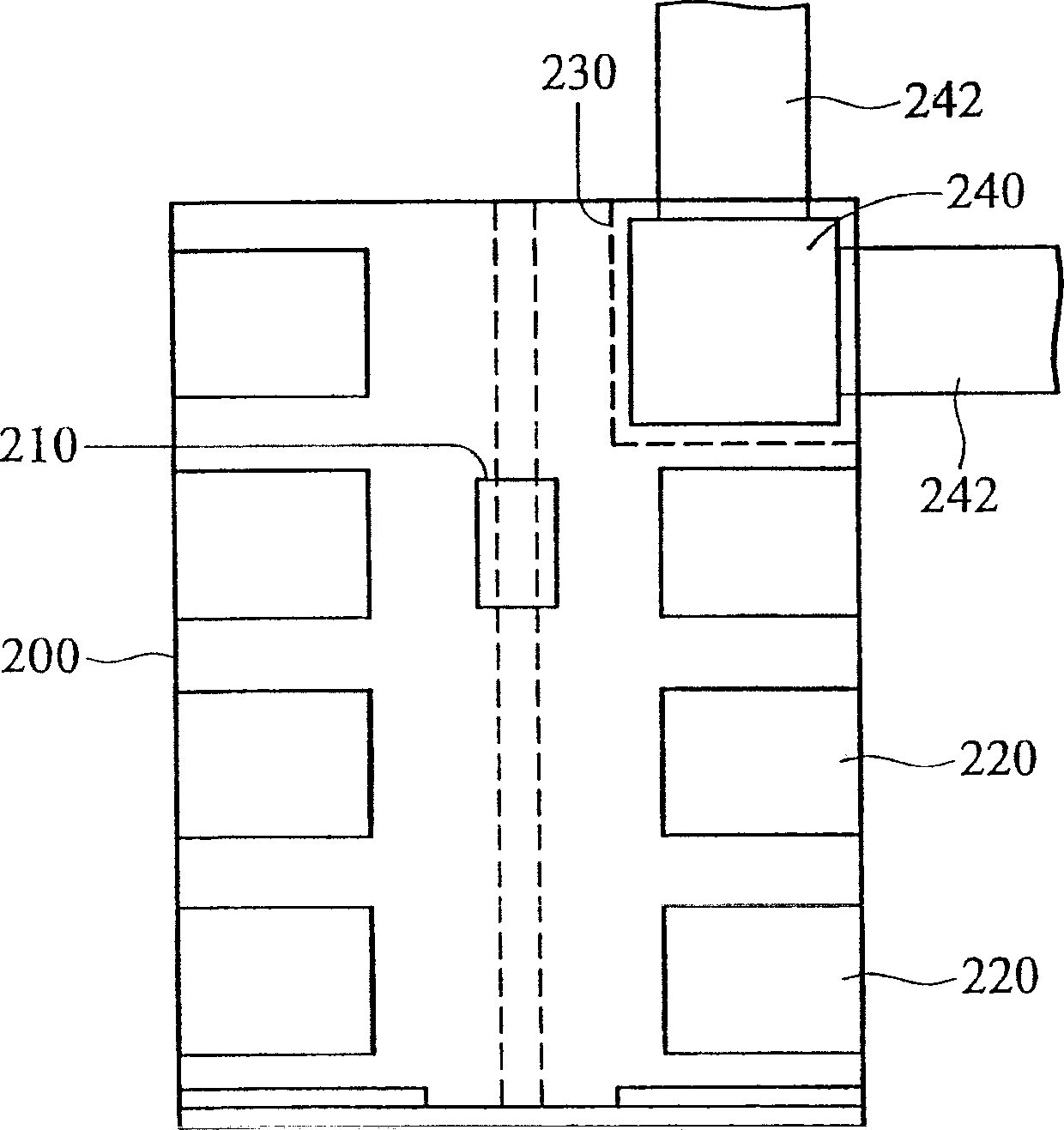
[0011] The first embodiment of the automated material handling system of the present invention is as Figure 2a As shown, it includes a conveying track (crane track) 242 , a conveying vehicle (cradle) 240 and a storage cabinet 200 . The transport vehicle 240 can move on the transport track 242 . The storage cabinet 200 includes a pick-and-place part 230 , and the pick-and-place part 230 is located in the storage cabinet 200 . Wherein, the conveying track 242 extends into the storage cabinet 200 and overlaps with the pick-and-place part 230. When the conveying vehicle 240 is located at the pick-and-place part 230, the transfer machine 210 directly puts materials into the conveying vehicle 240 middle.

[0012] When materials are to be moved from the storage cabinet 200 to the crane 240, the transfer machine 210 first takes the materials out of the storage compartment 220, and then transports them to the pick-and-place unit 230, and directly places the materials on the crane 24...


PUM


Abstract

The invention discloses a automatic material lifting system, it includes a transporting trail(crown block trail), a transporting vehicle(crown block) and a storage. The transporting vehicle can move on the trail. The storage includes a taking and putting part, which is in the storage. The transporting trail enters into the storage, and overlaps with the taking and putting part, when the transporting vehicle is in the taking and putting part, the moving loading machine puttes the material into the transporting vehicle.

Description

technical field [0001] The invention relates to an automatic storage system, in particular to an automatic storage system that can flexibly plan space and be applied to smaller factory areas. Background technique [0002] During the handling process of the previous Automated Material Handling System (Automated Material Handling System, AMHS), the connection between storage cabinets is usually achieved through an Overhead Shuttle (OHS). refer to Figure 1a , which is a top view of an existing automated material handling system. The storage cabinet 100 has a transfer machine 110 , a plurality of storage compartments 120 and a pick-and-place unit 130 . The pick and place unit 130 has rollers 135 . The transfer machine 110 takes out materials from the storage compartment 120 , and then transports the materials to the pick-and-place unit 130 , and the materials can be transferred to the crane 140 through the conveying of the rollers 135 . The overhead crane 140 utilizes the ove...

Claims


Application Information

Patent Timeline
Patent Type & Authority Applications(China)
IPC IPC(8): B65G1/04B66C11/06
Inventor 陈宏伟张玉彦
Owner AU OPTRONICS CORP
Why Eureka
Try Eureka