
Space rotary alternating magnetic field demagnetizing pole set

A technology of alternating magnetic field and space rotation, applied in the direction of magnetic objects, electrical components, circuits, etc., can solve the problem of impossible to solve the problem of diversification of residual magnetism of the workpiece, increasing the difficulty of determining the magnetization direction of the workpiece, and poor demagnetization effect.

Inactive Publication Date: 2005-02-16
夏恽
View PDF0 Cites 1 Cited by
  • Summary
  • Abstract
  • Description
  • Claims
  • Application Information

AI Technical Summary

Problems solved by technology

Because the magnetization of the workpiece and the direction of the residual magnetism in the processing process are affected by many factors, such as the shape of the workpiece, the magnetization method, the diffraction and decomposition of the residual magnetism and other factors, the direction of the residual magnetism may be diversified, which greatly increases the difficulty of determining the magnetization direction of the workpiece.
However, the currently used demagnetizers form an alternating magnetic field in a single direction, so demagnetization in a single direction cannot solve the diversification of the residual magnetism direction of the workpiece.
Therefore, it is impossible to demagnetize the workpiece with multiple magnetization, and the demagnetization effect is poor

Method used


Image

  • Space rotary alternating magnetic field demagnetizing pole set
  • Space rotary alternating magnetic field demagnetizing pole set
  • Space rotary alternating magnetic field demagnetizing pole set

Examples


Embodiment Construction

[0012] In conjunction with accompanying drawing, provide embodiment of the present invention as follows:

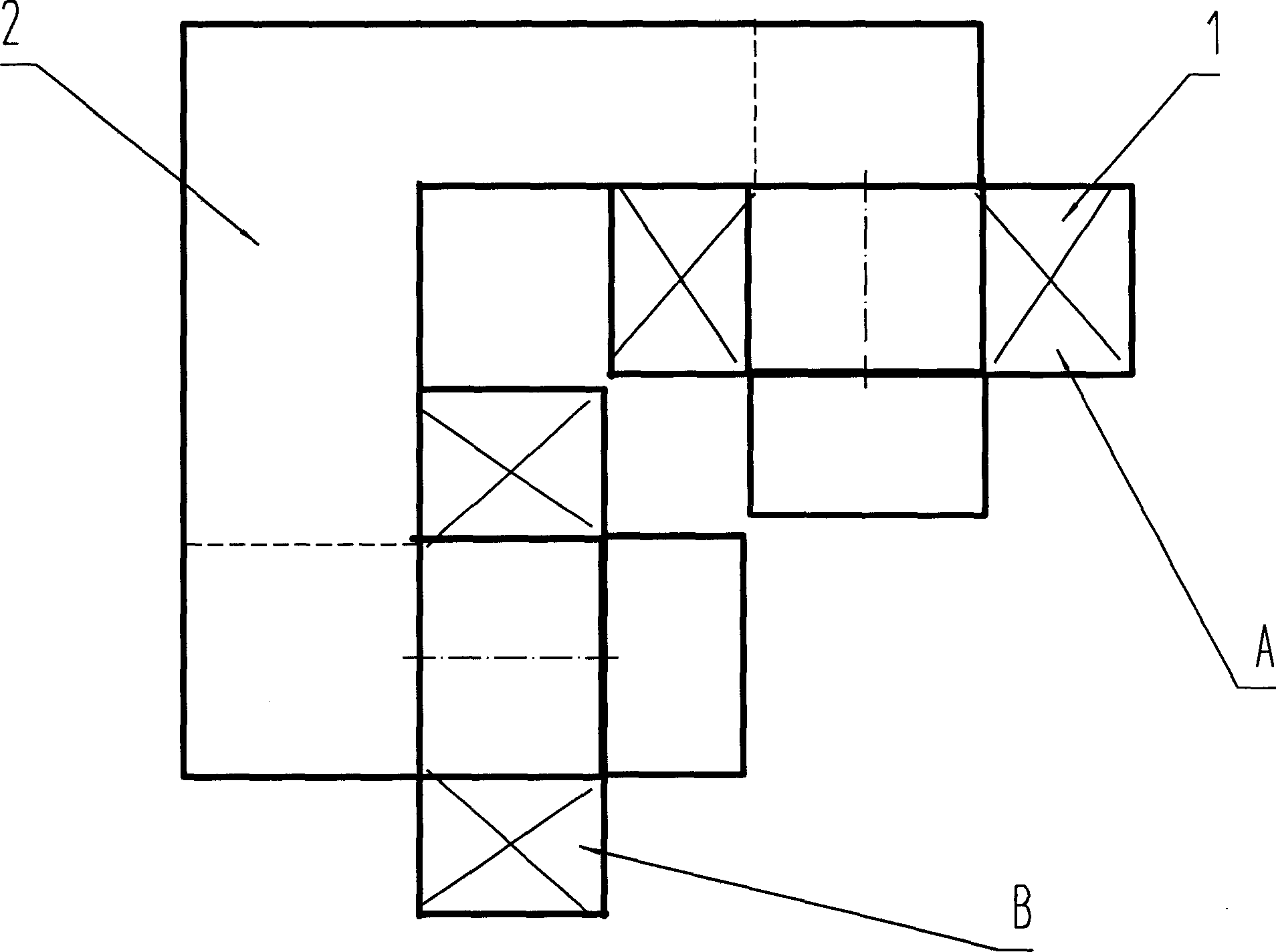
[0013] Such as figure 1 The one shown adopts a group of two-phase demagnetization pole groups, which is composed of magnetic pole A and magnetic pole B. The coil 1 installed on the iron core 2 is connected to the two-phase power supply. The two demagnetization poles are on the same plane, and the included angle is 90 degrees.

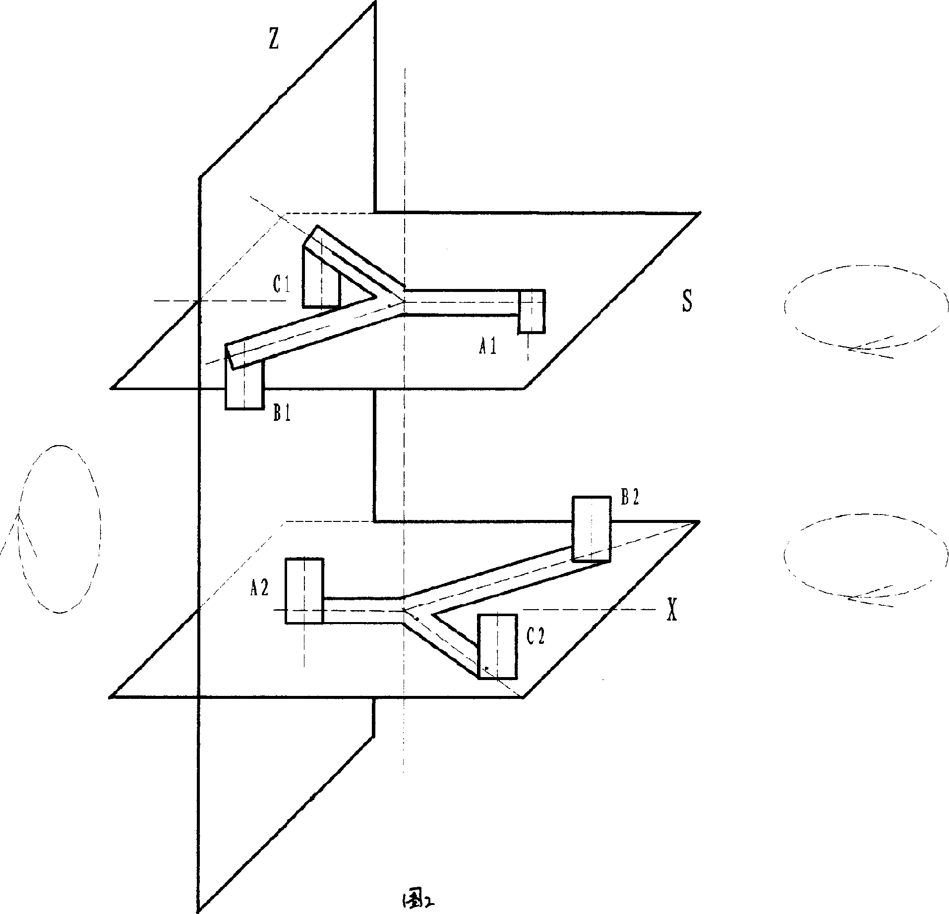
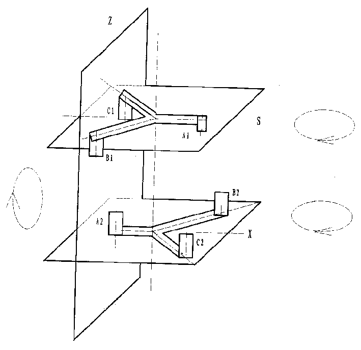
[0014] As shown in Figure 2, two sets of demagnetization pole groups are used. Each set of demagnetization sets consists of three magnetic poles. The demagnetization coils are arranged in a "Y"-shaped array, or a "△"-shaped array. A1 is formed on the S surface. , B1, C1 three magnetic poles, there are A2, B2, C2 three magnetic poles on the X surface, the three magnetic poles form a plane rotating magnetic field, and the coils on the three magnetic poles pass through the three-phase AC power supply. The corresponding poles of the S plane and the X ...


PUM


Abstract

Disclosed demagnezing pole subassembly of spatial rotating alternating magnetic field includes one or two groups, and one demagnezing pole group includes multiple demagnezing poles. Being connected to AC power source in certain phase, pole winding is installed onto magnetic iron core constitutes a magnetic pole. Demagnezing poles are distributed in array, and each demagnezing pole is connected to AC power source in different phases. There are certain spatial distances between magnetic poles in demagnezing device so as to form spatial rotating alternating magnetic field. Thus, there are demagnetizing fields in space in any direction so that direction of residual magnetism in work piece does not need to be determined in advance. The invention raises demagnezing efficiency, applicable to fields such as milling process, detection of defects, precision work, instrument and meters.

Description

Technical field [0001] The invention relates to fields with specific requirements for residual magnetism in grinding, flaw detection, precision machining, instrumentation, etc., and mainly relates to a space rotating alternating magnetic field demagnetization pole group. Background technique [0002] The demagnetization process is to disturb the magnetization to cause the direction consistency of the magnetic domains, and restore the magnetic neutral state of the disordered direction before the magnetic domains are not magnetized. There are two current demagnetization methods, one is heat treatment demagnetization method, and the other is diamagnetic field demagnetization method. The heat treatment demagnetization method is to heat the demagnetized workpiece above the Curie temperature point, so that the magnetism becomes paramagnetic and loses its magnetism. The anti-magnetic field demagnetization method has two necessary conditions, that is, the direction of the demagneti...

Claims


Application Information

Patent Timeline
IPC IPC(8): H01F13/00
Inventor 夏恽
Owner 夏恽
Learn More