Chain driven slide automatic air valve

A chain drive and damper technology, which is used in mine/tunnel ventilation, mining equipment, earth-moving drilling, etc., can solve problems such as burnout, inaccurate transmission force and transmission position, and difficulty in accurately controlling the damper load.

Inactive Publication Date: 2005-03-02
陈树林
View PDF0 Cites 7 Cited by
  • Summary
  • Abstract
  • Description
  • Claims
  • Application Information

AI Technical Summary

Problems solved by technology

The disadvantages of this kind of transmission are: 1. Due to the existence of "slipping", its transmission force and transmission position are not accurate, so it is difficult to accurately control the pulling force of the damper and the load of the motor, and often the damper cannot be pulled or the motor is overloaded. Burnout fault; 2. "Slipping" has strong wear on the driving wheel and the infinite rope; 3. Since the winding of the infinite rope on the "V" groove overlaps for half a circle, there will often be a rope biting fault that will cause the transmission to fail

Method used


Image

  • Chain driven slide automatic air valve

Examples


Embodiment Construction

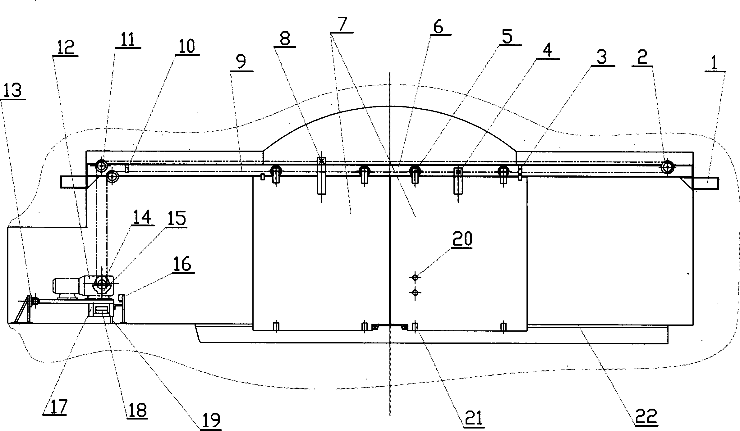
[0005] Excavate air door chambers on both sides of the roadway where the air door is installed, and guide rail supports (1) are pre-buried on the top of both ends of the chamber, and I-beam guide rails (6) are installed on the supports, and two push-pull air doors (7) It is hoisted on the I-shaped steel guide rail by means of rollers (5), and a trench is arranged on the floor at the lower end of the damper, and lower rails (22) are buried on both sides of the trench, and the two air doors are stuck between the two lower rails. Vertical roller (21) is equipped with at damper lower end, and damper slides between two slide rails under the guide action of vertical roller. The right end of guide rail (6) is installed right to change sprocket wheel (2), is installed with left upper change sprocket wheel (11) and left lower change sprocket wheel at the left end of guide track. Install the swing machine base (17) on the floor of the chamber on the left side, the left end of the machin...


PUM


Abstract

The invention relates to a kind of chain transmitting push-and-draw automatic air door. Its characteristic is as the following: the air door adopts suspending structure with the top guide, roller chain drawing, tis roller driving device is fixed on the machine seat that swing from head to foot; under the machine seat establishes load adjusting device that can limit the greater pulling load of the roller, the limitation is realized through adjusting the pressure of heavy hammer and spring which can limit the machine seat from swinging up; above the machine seat are the overload limit-location switch which cooperates with load adjusting device to realize exact overloading protection; under the air door establishes vertical roller which runs along the sliding rails fixed on both side of the air door. On the air door there are photosensitive sensor which matches with computer to realize automatic control. The whole transmission structure is simple and reliable, the drag force of the transmission is small, its transmitting location and overloading control are accurate.

Description

technical field [0001] The chain-driven push-pull automatic damper of the present invention belongs to the damper for controlling ventilation in mines or tunnels. Background technique [0002] Motor drive has the advantages of high transmission efficiency, simple structure, and easy automatic control. But the electric automatic damper of prior art is to adopt endless rope transmission, and its structure is: on the output shaft of speed reducer, a drive wheel with " V " shape groove is installed, and endless rope is formed by a head-to-tail ring connection. Steel wire rope ring, one end of the endless rope is wound on the "V" groove of the driving wheel for one and a half weeks, and the other end of the endless rope uses a sheave equipped with a spring to tighten the endless rope. The driving wheel constitutes a friction transmission, and the two air doors are respectively stuck on the upper and lower endless ropes, and are dragged by the endless ...

Claims


Application Information

Patent Timeline
Patent Type & Authority Applications(China)
IPC IPC(8): E21F1/10E21F1/12
Inventor 陈树林
Owner 陈树林
Why Eureka
Try Eureka