Overload protection method, control method, device and wind power converter

An overload protection, overload current technology, applied in emergency protection circuit devices, emergency protection circuit devices for limiting overcurrent/overvoltage, measurement devices, etc., can solve the overload protection and overload protection detection logic of power electronic devices that cannot be powered Imperfect and other problems, to achieve the effect of improving the overload protection capability

Active Publication Date: 2022-05-10
维谛新能源有限公司
View PDF14 Cites 0 Cited by
  • Summary
  • Abstract
  • Description
  • Claims
  • Application Information

AI Technical Summary

Problems solved by technology

However, the current method used for overload protection cannot effectively protect power electronic devices from overload because the detection logic corresponding to overload protection is not perfect.

Method used


Image

  • Overload protection method, control method, device and wind power converter
  • Overload protection method, control method, device and wind power converter
  • Overload protection method, control method, device and wind power converter

Examples


Embodiment 1

[0137] See Figure 12 , is a schematic structural diagram of a grid-side module provided by an embodiment of the present disclosure. Taking a 2.1MW double-fed wind power converter grid-side power module as an example, the grid-side power module includes a three-winding transformer 121, a main switch 122, The main contactor 123, the generator 124, the LCL filter 125, the power device under test 126 at the grid side, the power device under test 127 at the rotor side and the control device 128, the main switch 122 and the main contactor 123 are connected in series to the three The winding transformer 121 and the generator 124; the LCL filter 125, the power device under test 126 at the grid side and the power device under test 127 at the rotor side are connected in series to the three-winding transformer 121 and the generator 124; The control device 128 is connected with the grid side power device under test 126 and the rotor side power device under test 127 . The wind power conv...

Embodiment 2

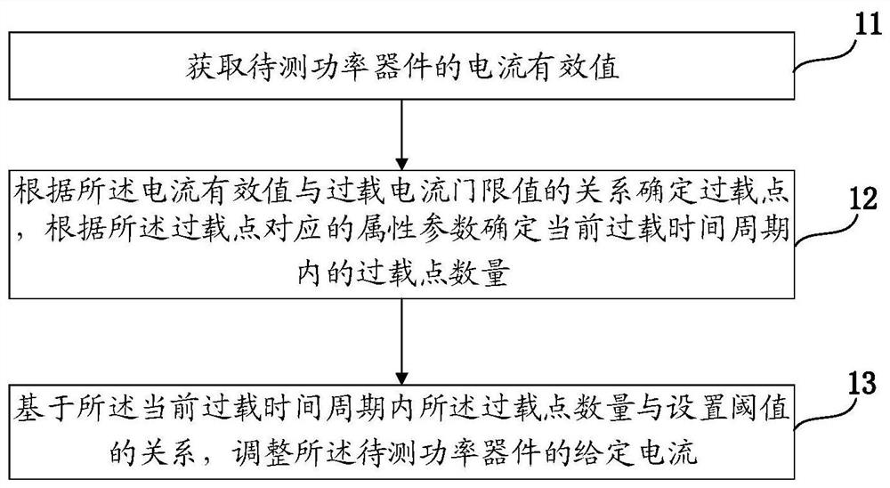
[0158] Step a1: The grid-side module collects the instantaneous current value of the power device under test according to the set frequency through the collector. The current frequency is 50Hz, and the set frequency is 3000Hz.

[0159] Step a2: The effective value calculator calculates the number of sampling points in each current cycle according to the frequency of the current and the set frequency when the instantaneous value is collected, and calculates the effective value of the current. Here, 60 points are collected in each current cycle, and the square root of the square sum of these 60 points is calculated to obtain the current effective value of the grid-side module.

[0160] Step a3: Determine whether the effective value of the current is greater than the upper limit of the overload current 450A, if yes, execute step a4; if not, execute a5.

[0161] Step a4: The current limiting regulator adjusts the current setting to an overload current threshold value of 450A.

...


PUM


Abstract

The embodiment of the present disclosure discloses an overload protection method, including: obtaining the current effective value of the power device to be tested; determining the overload point according to the relationship between the current effective value and the overload current threshold value; The parameters determine the number of overload points in the current overload time period; based on the relationship between the number of overload points in the current overload time period and the set threshold, adjust the given current of the power device under test. The embodiment of the present disclosure further discloses a control method, device and wind power converter with strong overload protection capability. In the embodiment of the present disclosure, it can be accurately known whether the power device under test is overloaded in the current overload time period, and the given current of the power device under test can be adjusted according to the overload situation, so that the power device under test can be accurately performed. Overload protection, thus effectively improving the overload protection capability of power devices.

Description

technical field [0001] Embodiments of the present disclosure relate to the field of overload protection, and in particular, to an overload protection method and device, a power device control method and device, and a wind power converter. Background technique [0002] Power electronic devices have the characteristics of controllability, high power, and high voltage, and are widely used in industrial and civil fields, such as wind power generation, solar power generation, steel rolling mills, paper machines, elevators, inverter air conditioners, washing machines, etc. IGBT is a representative of power electronic devices. The withstand voltage of a single IGBT can reach more than 1000V, and the withstand current can reach more than 300A. Power electronic devices work under the conditions of high voltage and high current, and turn on and off through the driving circuit to perform power conversion. Power devices will generate conduction loss during the conduction process and sw...

Claims


Application Information

Patent Timeline
Patent Type & Authority Patents(China)
IPC IPC(8): H02H9/02G01R19/165G01R31/26
CPCH02H9/02G01R31/2608G01R19/16519
Inventor 雷博
Owner 维谛新能源有限公司
Why Eureka
Try Eureka