Overload protection motor for load-carrying machinery
What is Al technical title?
Al technical title is built by PatSnap Al team. It summarizes the technical point description of the patent document.
A technology for overload protection and heavy-duty machinery, which is applied in the direction of electromechanical devices, mechanical energy control, electrical components, etc., can solve the problems of long response time and high cost, and achieve the effect of tight connection
Inactive Publication Date: 2021-08-10
王显正
View PDF0 Cites 2 Cited by
Summary
Abstract
Description
Claims
Application Information
AI Technical Summary
This helps you quickly interpret patents by identifying the three key elements:
Problems solved by technology
Method used
Benefits of technology
Problems solved by technology
The invention is mainly used to solve the problem of long response time and high cost in the prior art by adding detection and control elements in the circuit where the motor is located, and then realizing power-off overload protection
Method used
Image
Click on the blue label to locate the original text in one second.
Reading with bidirectional positioning of images and text.
Examples
Embodiment Construction
[0039] In order to make the technical means, creative features, goals and effects achieved by the present invention easy to understand, the present invention will be further described below in conjunction with specific embodiments.
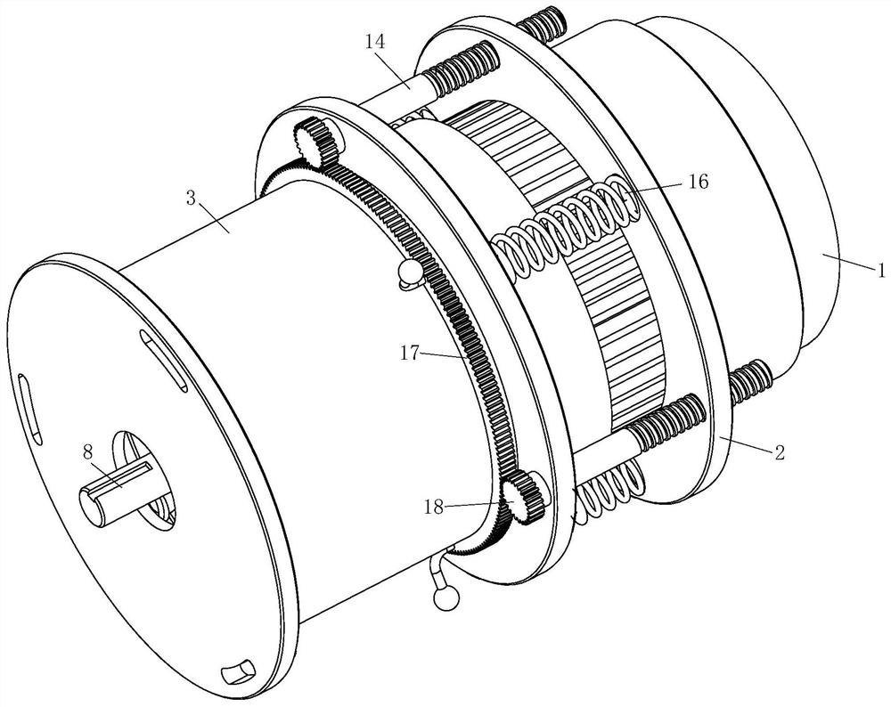
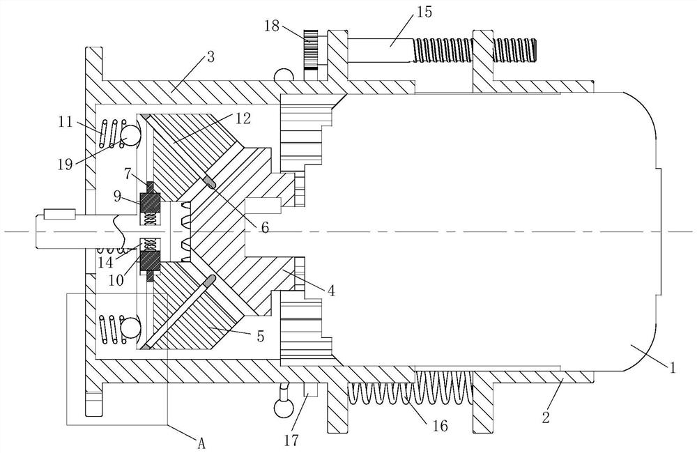
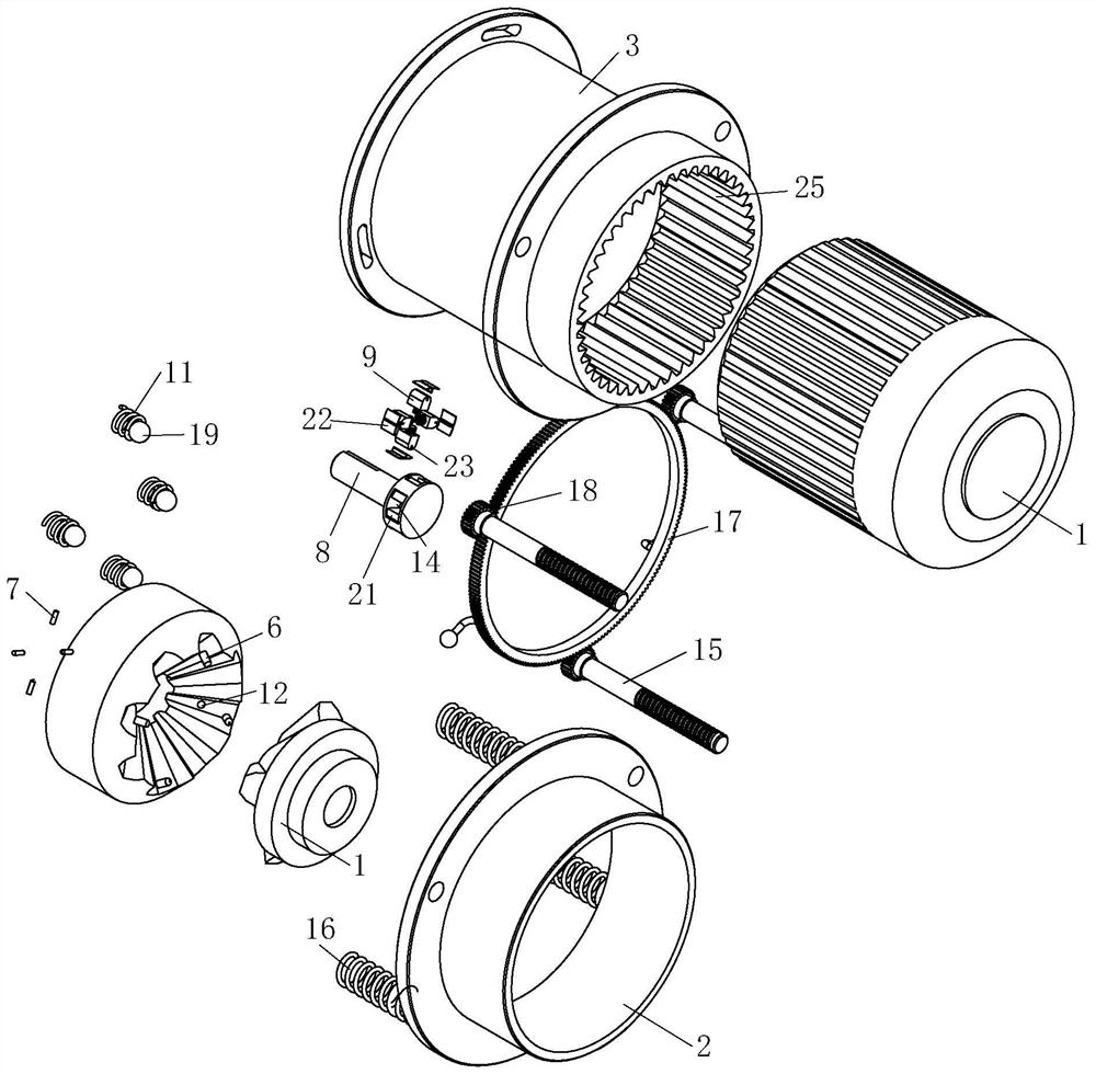
[0040] like Figure 1 to Figure 12 As shown, an overload protection motor for heavy-duty machinery includes a drive motor 1, a fixed seat 2, a movable seat 3, a No. 1 connector 4, a No. 2 connector 5, a No. 1 bump 6, a No. 2 bump 7, an Shaft 8, stopper 9, No. 1 spring 10 and No. 2 spring 11; the outside of the drive motor 1 is provided with the fixed seat 2; the fixed seat 2 is fixedly connected with the drive motor 1; the fixed One side of the seat 2 is provided with the movable seat 3; the movable seat 3 is interactively connected with the drive motor 1; the movable seat 3 is coaxial with the fixed seat 2; the drive motor 1 is close to the One end of the movable seat 3 is provided with the No. 1 connector 4; one end of the No. 1 connector 4 is ...
PUM
Abstract
The invention belongs to the technical field of motors, and particularly relates to an overload protection motor for load-carrying machinery, which comprises a driving motor, a fixed seat, a movable seat, a first connecting piece, a second connecting piece, a first convex block, a second convex block, an output shaft, a stop block, a first spring and a second spring. When the output shaft is locked, the driving motor drives the first connecting piece to rotate relative to the second connecting piece, so that teeth on the first connecting piece are meshed with the tooth surface, provided with the first convex block, of the second connecting piece, the first convex block is compressed into the pressure cavity, and the second convex block at the other end of the pressure cavity is extruded out; the stop block completely enters the sliding groove in the output shaft, then the output shaft and the second connecting piece are not restrained in the rotating direction, then the motor is separated from a force transmission path of the load end through a mechanical structure, overload protection of the motor is achieved, the structure is simpler, the number of needed parts is smaller, and cost is lower.
Description
technical field [0001] The invention belongs to the technical field of electric motors, in particular to an overload protection electric motor for heavy-duty machinery. Background technique [0002] Motor refers to an electromagnetic device that realizes the conversion or transmission of electric energy according to the law of electromagnetic induction. Its main function is to generate driving torque as a power source for electrical appliances or various machines; it can be divided into DC according to the type of working power supply: Motor and AC motor; can be divided according to structure and working principle: can be divided into DC motor, asynchronous motor, synchronous motor; can be divided according to starting and running mode: capacitor starting type single-phase asynchronous motor, capacitor running single-phase asynchronous motor, capacitor Start-up and running single-phase asynchronous motors and split-phase single-phase asynchronous motors; can be divided by us...
Claims
Application Information
Patent Timeline
Application Date:The date an application was filed.
Publication Date:The date a patent or application was officially published.
First Publication Date:The earliest publication date of a patent with the same application number.
Issue Date:Publication date of the patent grant document.
PCT Entry Date:The Entry date of PCT National Phase.
Estimated Expiry Date:The statutory expiry date of a patent right according to the Patent Law, and it is the longest term of protection that the patent right can achieve without the termination of the patent right due to other reasons(Term extension factor has been taken into account ).
Invalid Date:Actual expiry date is based on effective date or publication date of legal transaction data of invalid patent.