Star dividing difference time spaced modulation and demodulation method for quick fading channel

A split differential and space-time modulation technology, which is applied in the direction of preventing/detecting errors through diversity reception, and can solve the problems of differential unitary space-time modulation and demodulation methods not applicable to data transmission, large Doppler frequency shift, and system performance deterioration, etc. question

Inactive Publication Date: 2005-03-02
SHANGHAI JIAO TONG UNIV
View PDF0 Cites 3 Cited by
  • Summary
  • Abstract
  • Description
  • Claims
  • Application Information

AI Technical Summary

Problems solved by technology

In fast fading channels, the Doppler frequency shift is very large, which leads to a long time interval between two adjacent space-time symbols in differential unitary space-time modulation and demodulation, so the channel fading corresponding

Method used


Image

  • Star dividing difference time spaced modulation and demodulation method for quick fading channel
  • Star dividing difference time spaced modulation and demodulation method for quick fading channel
  • Star dividing difference time spaced modulation and demodulation method for quick fading channel

Examples


Embodiment Construction

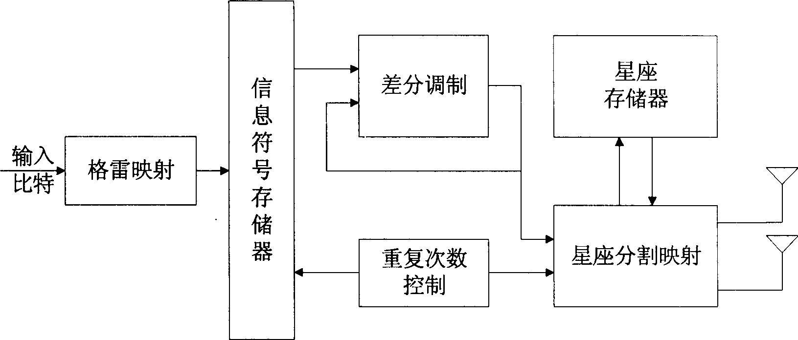
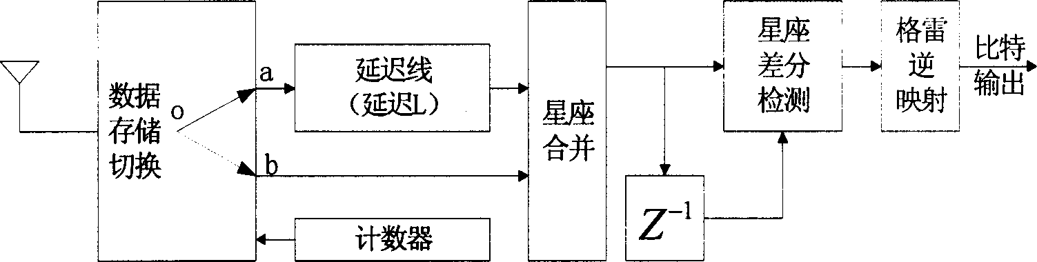
[0022] like figure 1 , figure 2 Shown, provide following embodiment in conjunction with content of the present invention:

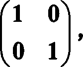
[0023] This embodiment adopts a two-transmit-one-receive structure, that is, the transmitting end adopts two transmitting antennas, and the receiving end adopts one receiving antenna. The data transfer rate is 2 bits / s / Hz, figure 1 The following four constellation matrices are pre-stored in the shown constellation memory: 1 0 0 1 , 0 - 1 1 0 , - 1 ...


PUM


Abstract

A modulation-demodulation method for constellation split difference empty time of quick decline channels includes methods of modulation and demodulation of constellation split difference empty time. The modulation method includes: acquiring original difference empty time constellation matrix to be divided into several sub-matrixes in terms of time shaft to be carried out in equal time interval delay in light of the data frame length to be emitted to corresponding antennas. The demodulation method includes: adopting coherent time delay to the data received in terms of time sequence to be merged to ensure the merged matrix is the equivalent received matrix of the original, finally to carry out difference empty time demodulation.

Description

technical field [0001] The invention relates to a differential space-time modulation and demodulation method used in the technical field of mobile communication, in particular to a constellation division differential space-time modulation and demodulation method suitable for fast fading channels. Background technique [0002] The rapid development of multimedia services and data networks requires future wireless communication systems to provide faster data transmission rates while ensuring communication quality, and to more effectively utilize existing spectrum resources. In the Rayleigh flat fading channel, the use of multi-antenna technology can effectively improve the spectrum utilization of the system. However, with the increase of the data transmission rate and the increase of the number of transmitting and receiving antennas, it becomes more and more difficult and complex to estimate the channel information timely and accurately at the receiving end. Moreover, as the ...

Claims


Application Information

Patent Timeline
IPC IPC(8): H04L1/06
Inventor 姜海宁田继锋罗汉文宋文涛
Owner SHANGHAI JIAO TONG UNIV
Why Eureka
Try Eureka