Control apparatus and method for inner cylinder direct injection spark ignited internal combustion engine

a technology of direct injection and internal combustion engine, which is applied in the direction of electric control, ignition automatic control, machines/engines, etc., can solve the problems of unestablished combustion stability, achieve the effect of reducing hc, strengthening turbulence, and shortening the combustion interval

Inactive Publication Date: 2008-04-01
NISSAN MOTOR CO LTD
View PDF16 Cites 25 Cited by
  • Summary
  • Abstract
  • Description
  • Claims
  • Application Information

AI Technical Summary

Benefits of technology

[0005]It is effective to retard the ignition timing in order to reduce HC (HydroCarbon) through the earlier activation of the catalytic converter (catalyst) and through an after burning of HC, during the cold start of the engine. In addition, it is desirable to perform an ignition at a timing after the compression stroke top dead center (an, so-called, ATDC ignition) in order to obtain a larger effect of reducing HC. It is necessary to shorten a combustion interval of time in order to have the engine perform a stable combustion by means of the ATDC ignition. In order to achieve this, it is necessary to strengthen a turbulence developed within an engine cylinder to strengthen a turbulence developed within an engine cylinder and raise a combustion speed (a flame propagation speed). In order to strengthen such a turbulence as described above, it may be considered that this turbulence is developed due to an energy of a fuel spray injected into an engine cylinder under a high pressure. However, in the technique disclosed in the above-described Japanese Patent, the first time injection (the earlier period injection) is carried out during a suction stroke and the second time injection (the later period injection) is carried out during 120° BTDC (Before Top Dead Center) through 45° BTDC in the compression stroke. In this way, since the later period fuel injection is carried out before the compression stroke top dead center, the turbulence is attenuated at a time after the compression stroke top dead center and does not contribute to a rise in the flame propagation speed by means of the ATDC ignition even if the fuel spray caused by the later period injection develops the turbulence within the engine cylinder.
[0008]It is, in view of the above-described current circumstances, an object of the present invention to provide control apparatus and method for the inner cylinder direct injection spark ignited internal combustion engine which can achieve an improvement in the combustion stability through the ATDC ignition for the earlier activation of the catalyst (catalytic converter) and a reduction of HC (HydroCarbon).

Problems solved by technology

However, a combustion stability is not established.

Method used


Image

  • Control apparatus and method for inner cylinder direct injection spark ignited internal combustion engine
  • Control apparatus and method for inner cylinder direct injection spark ignited internal combustion engine
  • Control apparatus and method for inner cylinder direct injection spark ignited internal combustion engine

Examples


first embodiment

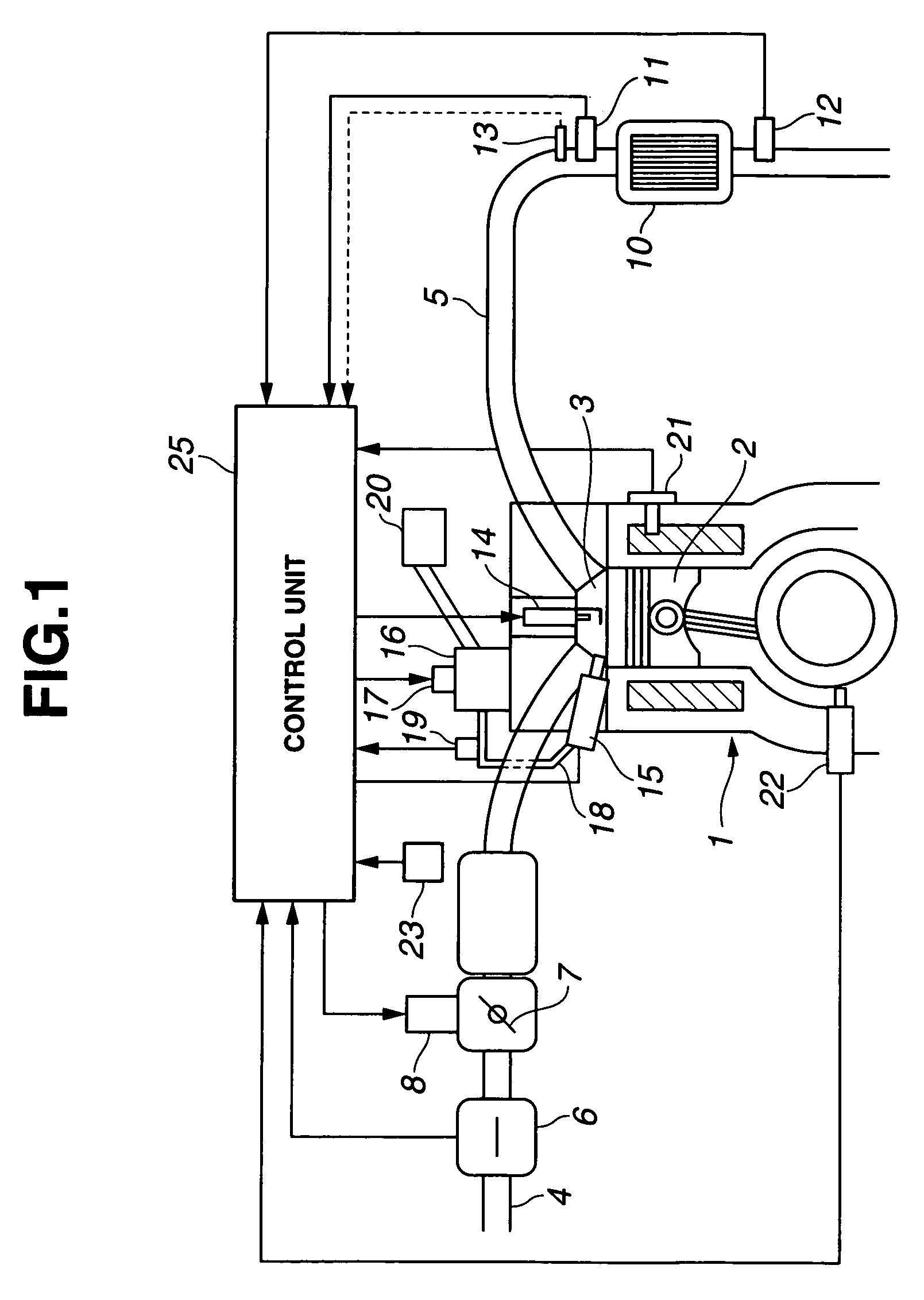
[0024]FIG. 1 shows a structural explanatory view representing a system configuration of an inner cylinder (or in-cylinder) direct injection spark ignited internal combustion engine to which a control apparatus in a first preferred embodiment according to the present invention is applicable.

[0025]An intake passage 4 is connected to a combustion chamber 3 via an intake valve (or intake valves). Combustion chamber 3 is formed by means of a piston 2 of an internal combustion engine 1. An exhaust passage 5 is connected to combustion chamber 3 via an exhaust valve (or exhaust valves). An airflow meter 6 is disposed in intake passage 4 which detects an intake air quantity and an electronically controlled throttle valve 7 whose opening angle is controlled via an actuator 8 in response to a control signal supplied thereto. An exhaust purifying catalytic converter 10 is disposed on exhaust passage 5. Air-fuel ratio sensors 11, 12 are disposed at upstream and downstream sides of catalytic conv...

second embodiment

[0050]A second preferred embodiment of the control apparatus for the inner cylinder direct injection spark ignited internal combustion engine according to the present invention will be described below. FIG. 1 and FIG. 2 are applicable to the second embodiment and the contents of the second embodiment are generally the same as the first embodiment described above. Hence, only difference points from the first embodiment will be described below.

[0051]As described above, in FIG. 1, pressure regulator 17 is configured to be enabled to vary the fuel pressure of fuel supplied to fuel injection valve 15 as fuel pressure varying means (a fuel pressure varying section) in a relatively wide range, in the second embodiment. Control unit 25 controls fuel pressure through pressure regulator 17 in addition to the other controls described in the first embodiment.

[0052]It is noted that, after the engine warm up is finished, in the predetermined low-speed-and-low-load region, the fuel injection is ca...

third embodiment

[0057]A third preferred embodiment of the control apparatus for the inner cylinder direct injection spark ignited internal combustion engine according to the present invention will be described below. FIG. 1 and FIG. 2 are applicable to the third embodiment and the contents of the third embodiment are generally the same as the first embodiment as described above. Hence, only difference points from the first embodiment will be described below.

[0058]In this embodiment, pressure regulator 17 constitutes the fuel pressure varying section (fuel pressure varying means) in the same way as the case of the second embodiment. Furthermore, in this embodiment, the fuel pressure when the super retard combustion is executed is controlled to make the fuel pressure higher as an engine speed is varied toward a higher speed side. More specifically, the fuel pressure becomes higher in proportion to a square of the engine speed. In order to perform the stable combustion in a high engine speed region, i...


PUM


Abstract

In control apparatus and method for an inner cylinder spark ignited internal combustion engine having a fuel injection valve configured to directly inject fuel into an inside of an engine cylinder and a spark plug, a super retard combustion is executed to set an ignition timing after a compression stroke top dead center and to inject fuel before the ignition timing and after the compression stroke top dead center during a predetermined engine driving condition and at least part of fuel is injected before the compression stroke top dead center to decrease a fuel injection quantity after the compression stroke top dead center during an interval which is immediately after an engine start and in which a pressure of fuel is relatively low.

Description

BACKGROUND OF THE INVENTION[0001](a) Field of the Invention[0002]The present invention relates to an inner cylinder direct injection spark ignited internal combustion engine and, more particularly, relates to control techniques on a fuel injection timing and an ignition timing at a time of a cold start of the engine demanding an earlier temperature rise (earlier activation) of a catalytic converter of an exhaust system in the internal combustion engine.[0003](b) Description of the Related Art[0004]A Japanese Patent No. 3325230 issued on Jul. 5, 2002 (which corresponds to a U.S. Pat. No. 6,345,499 issued on Feb. 12, 2002) describes a previously proposed technique in which, as a catalyst warming up method of the inner cylinder (in-cylinder) direct injection stark ignited internal combustion engine, at least twice (two times) split injections are carried out which include: a later period injection to form an air mixture fuel having a partial rich and lean air-fuel ratio within a combus...

Claims


Application Information

Patent Timeline
Patent Type & Authority Patents(United States)
IPC IPC(8): F02P5/00F02P5/04
CPCF02D37/02F02D41/0255F02D41/3836F02D41/402F02D41/401F02D2041/389F02D2200/0602F02D2200/0606Y02T10/44Y02T10/26Y02T10/12Y02T10/40
Inventor YASUNAGA, MAKOTOTAKEDA, TOMOYUKINAKAJIMA, AKIRAHORIKOMI, TAIZOTAKAKI, DAISUKEUCHIYAMA, KATSUAKIHIDAKA, MASATOSHIISHII, HITOSHISHIGEFUJI, TOMOYUKITOMITA, MASAYUKIAKAGI, MITSUHIRO
Owner NISSAN MOTOR CO LTD
Why Eureka
Try Eureka