Control device for exhaust gas sensor of internal-combustion engine

a control device and exhaust gas technology, applied in the direction of electrical control, instruments, material electrochemical variables, etc., can solve the problems of deteriorating characteristics of the air-fuel ratio sensor, and achieve the effect of reducing the time interval and stable outpu

Inactive Publication Date: 2005-02-10
TOYOTA JIDOSHA KK
View PDF4 Cites 25 Cited by
  • Summary
  • Abstract
  • Description
  • Claims
  • Application Information

AI Technical Summary

Benefits of technology

[0008] The present invention has been made to solve the above problems, and provides a control device that is used with an exhaust gas sensor of internal-combustion engine and capable of reducing the time interval between the instant at which the internal-combustion engine starts up and the instant at which the exhaust gas sensor generates a stable output.

Problems solved by technology

When the degree of such combination increases, the resistance of the sensor element increases, then the characteristic of the air-fuel ratio sensor deteriorates.

Method used


Image

  • Control device for exhaust gas sensor of internal-combustion engine
  • Control device for exhaust gas sensor of internal-combustion engine
  • Control device for exhaust gas sensor of internal-combustion engine

Examples


first embodiment

[0027] [Hardware Configuration of the First Embodiment]

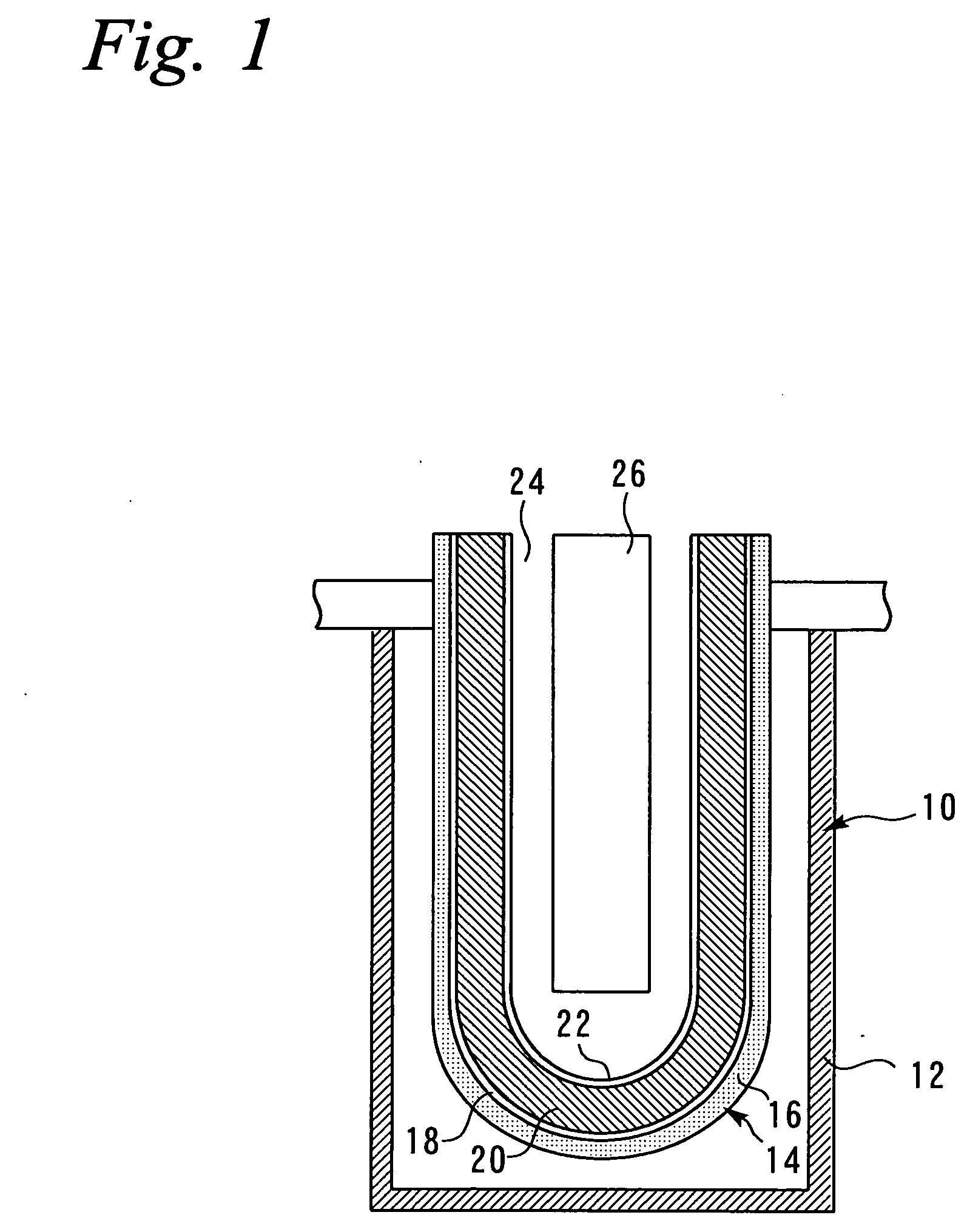
[0028]FIG. 1 illustrates the configuration of an air-fuel ratio sensor 10 that is used in a first embodiment of the present invention. The air-fuel ratio sensor 10 shown in FIG. 1 is positioned in an internal-combustion engine's exhaust path and used to detect the air-fuel ratio of the exhaust gas. The air-fuel ratio sensor 10 is provided with a cover 12. The cover 12 is mounted in the exhaust path in such a manner that it is exposed to the exhaust gas.

[0029] The cover 12 is provided with a hole (not shown) for introducing the exhaust gas inward. A sensor element 14 is positioned inside the cover 12. The sensor element 14 has a tubular structure whose one end (lower end in FIG. 1) is closed. The outer surface of the tubular structure is covered with a diffused resistor layer 16. The diffused resistor layer 16 is made of alumina or other heat-resistant porous substance. It controls the diffusion speed of the exhaust gas near the...


PUM

PropertyMeasurementUnit
activity temperatureaaaaaaaaaa
constant voltageaaaaaaaaaa
voltageaaaaaaaaaa

Abstract

Disclosed is a control device, which controls an air-fuel ratio sensor that is mounted in an exhaust path of an internal-combustion engine. The air-fuel ratio sensor is capable of pumping oxygen in a gas. Normally (time t0-t1, time t3 or later), a positive voltage Vp1 is applied to a sensor element (FIG. 7A), and the air-fuel ratio is calculated (FIG. 7C) in accordance with a sensor current (FIG. 7B). A heater is driven after internal-combustion engine startup to heat the sensor element. In a process in which the sensor element temperature rises, a negative voltage Vm, which is oriented in a direction different from that of the positive voltage Vp1, is applied to the sensor element.

Description

BACKGROUND OF THE INVENTION [0001] 1. Field of the Invention [0002] The present invention relates to a control device for an exhaust gas sensor of internal-combustion engine, and more particularly to a control device suitable for controlling an exhaust gas sensor that is equipped with a sensor element having a function for pumping oxygen in a gas. [0003] 2. Background Art [0004] A device for controlling an air-fuel ratio sensor, which is positioned in an exhaust path of an internal-combustion engine, is disclosed by Japanese Patent Laid-open No. Hei 9-101285. This device applies a predetermined positive voltage to the air-fuel ratio sensor's sensor element during an internal-combustion engine's operation. In this instance, the sensor element pumps oxygen in an exhaust gas, and causes an electrical current to flow in accordance with the amount of such pumping, that is, invokes the flow of a limiting current corresponding to the oxygen concentration in the exhaust gas. The oxygen conc...

Claims


Application Information

Patent Timeline
Patent Type & Authority Applications(United States)
IPC IPC(8): G01N27/41F01N3/00F01N13/00F01N99/00F02D35/00F02D41/22F02D45/00G01N27/406
CPCG01N27/4065
Inventor AOKI, KEIICHIROSUZUKI, YUSUKESAKAYANAGI, YOSHIHIRO
Owner TOYOTA JIDOSHA KK
Why Eureka
Try Eureka