

Defroasting method of air cooling heat pump system and its defroasting device
An air-cooled heat pump and condensing pressure technology, which is applied in the direction of refrigerators, refrigeration components, refrigeration and liquefaction, etc., can solve the problems of compressor capacity not being able to play, weak defrosting ability, etc., and achieve short defrosting time and strong defrosting ability , The effect of thorough defrosting
- Summary
- Abstract
- Description
- Claims
- Application Information
AI Technical Summary
Problems solved by technology
Method used
Image

Examples
Embodiment 1
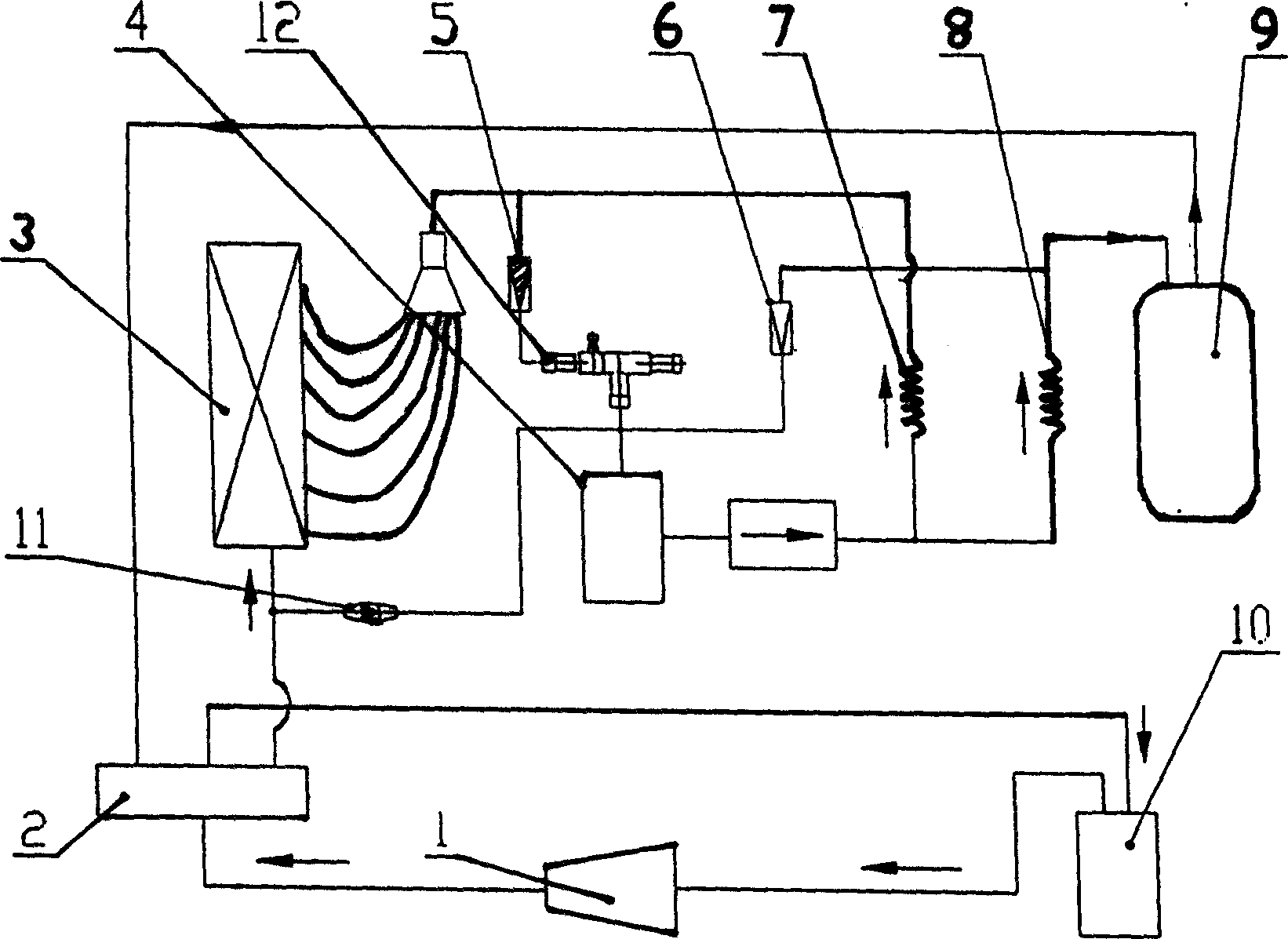
[0019] Such as figure 2 Shown. The air-cooled heat pump high-efficiency defrosting method described in this embodiment is to control the condensing pressure during the defrosting process. The condensing pressure is controlled by the combined action of a differential pressure control valve and a condensing pressure regulating valve, and the implemented defrosting device It includes an air-side heat exchanger 3 and an accumulator 4. A pressure control device is provided between the inlet and outlet of the air-side heat exchanger 3 and the inlet of the accumulator 4. The pressure control device includes a pressure difference controller 11 and Condensing pressure control valve 12, a pressure difference controller 11 is connected between the inlet of the air-side heat exchanger 3 and the inlet of the accumulator 4, and a condensing pressure is connected between the outlet of the air-side heat exchanger 3 and the inlet of the accumulator 4 Control valve 12. Compared with the general ai...
Embodiment 2
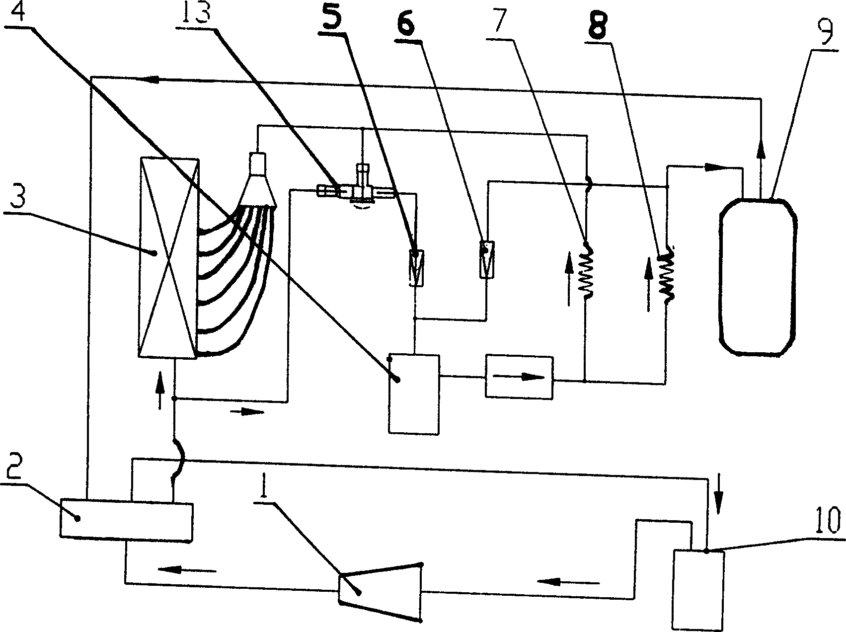
[0023] According to the different structure and performance of the valve parts that control the condensing pressure, the air-cooled heat pump system that adopts the condensing pressure control can be controlled by the condensing pressure control valve alone, such as image 3 As shown, the pressure control device described in this embodiment is a condensing pressure control valve 13, the inlet and outlet of the air-side heat exchanger 3 are two input ports of the condensing pressure control valve 13, and the output port of the condensing pressure control valve 13 is through a single The valve 5 is connected to the accumulator 4. It is characterized by the use of a single valve condensing pressure control valve 13 instead of the differential pressure control valve 11 and the condensing pressure regulating valve 12. The condensing pressure control valve 13 only reacts to changes in outlet pressure and opens when the outlet pressure rises. In addition to controlling the outlet pressur...
Embodiment 3
[0025] The defrosting method of the air-cooled heat pump system and the defrosting device described in this embodiment is that a one-way path is provided on the outlet of the air-side heat exchanger 3, the condensing pressure regulating valve 12, and the inlet of the accumulator 4 Valve 5, check valve 5 can be as figure 2 As shown, set at the inlet of the condensing pressure regulating valve 12, it can also be as Figure 4 As shown, set at the outlet of the condensing pressure regulating valve 12, the outlet position of the differential pressure control valve 11 can be located between the one-way valve 5 and the accumulator 4, or between the condensing pressure regulating valve 12 and the one-way valve 5. It can also be located between the condensing pressure regulating valve 12 and the inlet of the accumulator 4.
PUM
 Abstract
Description
Claims
Application Information