Eureka AIR delivers breakthrough ideas for toughest innovation challenges, trusted by R&D personnel around the world.

Wire-and-tube evaporator

An evaporator and wire-tube type technology, applied in the field of wire-tube type evaporators, can solve the problems of technical design, i.e. difficulty in structural design, influence on the working efficiency of a refrigeration device, and defrosting dependent on the external environment, etc. Short cream time, enhanced effect

Inactive Publication Date: 2010-10-13
JIANGSU GELIN ELECTRIC APPLIANCE
View PDF17 Cites 4 Cited by
  • Summary
  • Abstract
  • Description
  • Claims
  • Application Information

AI Technical Summary

Problems solved by technology

However, the wire tube evaporator also has shortcomings, that is: defrosting depends on the external environment, more specifically, when the frost accumulated on the surface of the evaporating tube is to be removed, the door of the freezer is usually opened, and the outside air is exchanged with the evaporator. heat to melt the frost accumulated on the surface of the evaporator
Although this original defrosting method can play the role of defrosting, that is, to achieve the purpose of defrosting, the defrosting process is long and affects the working efficiency of the refrigeration device.
In addition, there is also a prejudice in the industry, that is, it is difficult or even impossible for the wire tube evaporator to be equipped with an electric heating element to help defrost, because the electric heating element cannot be integrally or consistently accompanied by the curved evaporator. Evaporation tubes are difficult in technical design, that is, in structural design

Method used


Image

  • Wire-and-tube evaporator
  • Wire-and-tube evaporator

Examples


Embodiment Construction

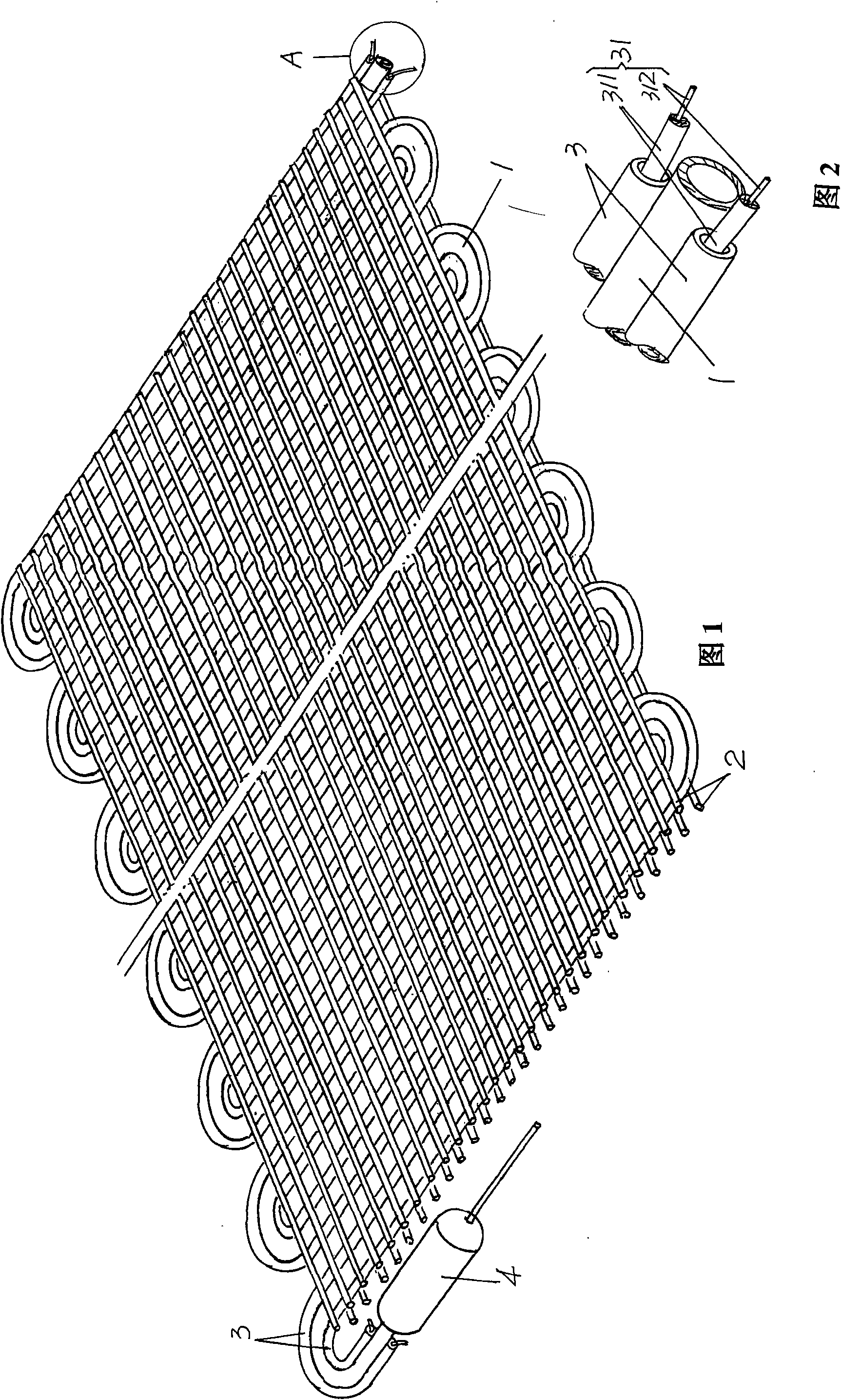
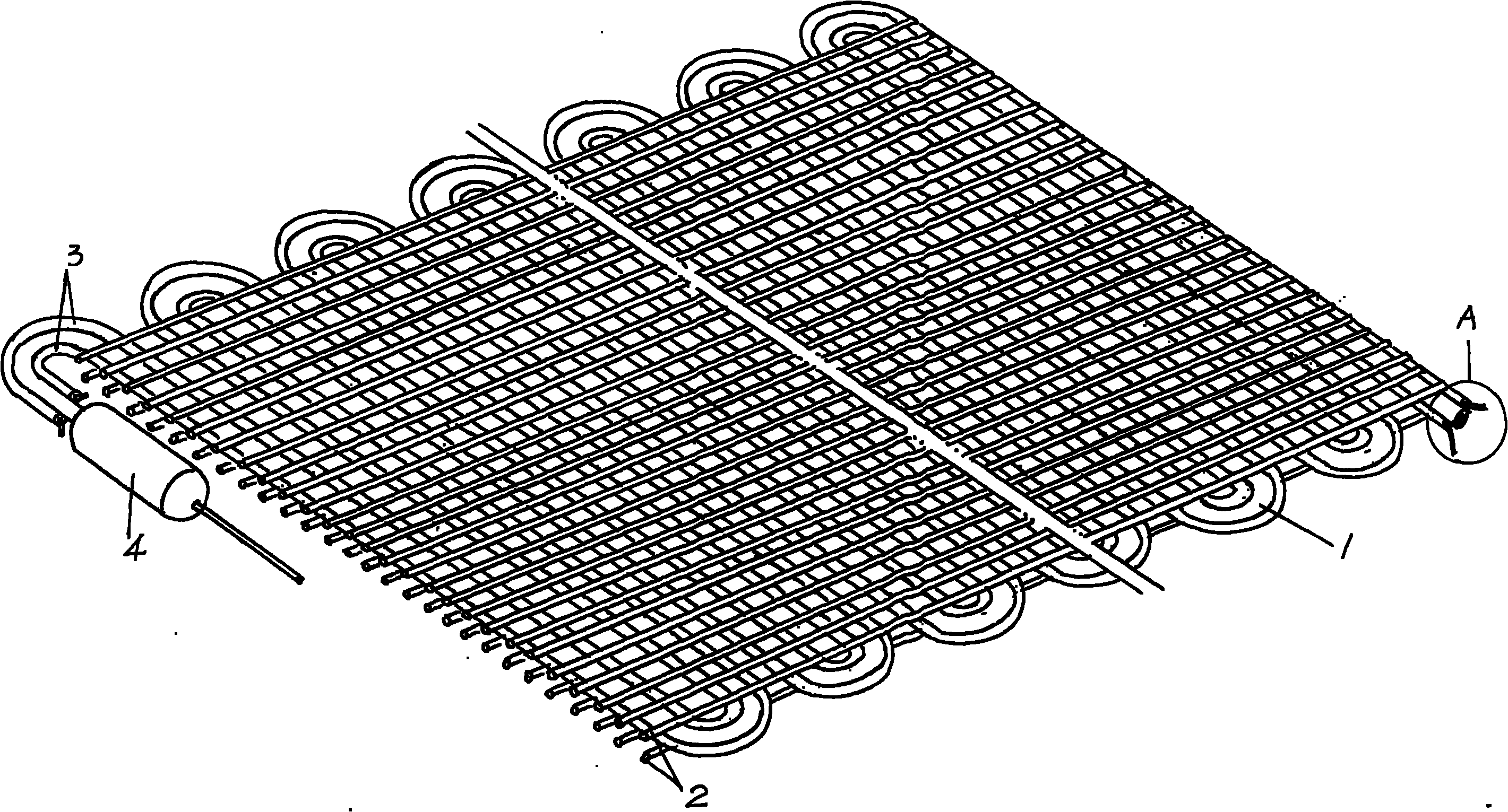
[0015] please see figure 1 and figure 2 , the given evaporating tube 1 is meandering and serpentine. In the present embodiment, the number of the evaporating tube 1’s twists and turns does not need to be limited, because it can be shown according to refrigeration devices such as refrigerators, refrigerated refrigerators, etc. Depending on the size of the cabinet or freezer (increase or decrease), the size of each zigzag is the same. The evaporating tube 1 is preferably an iron tube with a copper-plated layer on the surface, that is, a copper layer is plated on the surface of the iron tube. In this embodiment, there are two wires 2, each of which is fixed to the upper side and the lower side of the evaporating tube 1 by spot welding. More specifically, with the current figure 1 The position state shown is an example, the surface of the upward side of the evaporation tube 1 is fixed (fixed by spot welding) with a group of metal wires 2 in a grid state, and the surface of the...


PUM


Abstract

The invention provides a wire-and-tube evaporator, belonging to the technical field of a refrigerating apparatus. The wire-and-tube evaporator comprises an evaporation tube which is roundabout and snakelike and metal wires which are combined on at least one side of the evaporation tube in a grid shape. The wire-and-tube evaporator is characterized in that the outer wall of the evaporation tube is combined with an electric heating wire pipe which has the same winding shape with the evaporation tube and accompanies with the evaporation tube all the time, and the electric heating wire pipe is internally inserted with an electric heating wire. In the invention, as the electric heating wire pipe inserted with the electric heating wire always accompanies with the evaporation tube, when the power supply of the electric heating wire is switched on while defrosting, the electric heating wire heats the electric heating wire pipe to melt frosts concentrated on the surface of the evaporation tube, thus achieving short defrosting time and good overall defrosting effect; when the evaporation tube is in a working condition, the electric heating wire pipe makes an effect on enlarging evaporation area; in addition, and the electric heating wire pipe has good enhancement effect on the evaporator tube so as to achieve firm overall structure.

Description

technical field [0001] The invention belongs to the technical field of refrigeration devices, and in particular relates to a wire tube evaporator. Background technique [0002] The evaporator can be roughly divided into the following five categories from the form shown by its structure: one is the plate evaporator. The so-called plate evaporator is to lay the evaporation tube on the evaporation plate. The typical structure is the combined adjustable evaporator proposed by CN2123041U. The tube-plate evaporator equipped with casing and CN2171822Y; the second is a tube-type evaporator, and the so-called tube-type evaporator is formed by bending a simple evaporation tube, such as the improved refrigerator-freezer evaporator recommended by CN2793647Y; three It is a wire plate evaporator between a plate evaporator and a wire tube evaporator, a representative example is the refrigerator with a wire plate structure evaporator introduced by CN2722143Y; the fourth is a finned evaporat...

Claims


Application Information

Patent Timeline
Patent Type & Authority Applications(China)
IPC IPC(8): F25B39/02F25B47/00F28F21/08
Inventor 王伟俞仲良
Owner JIANGSU GELIN ELECTRIC APPLIANCE
Why Eureka
Eureka Blog
Learn More