
Tuyere duct system used for side window defrosting

An air duct and tuyere technology, applied in the field of tuyere air duct system, can solve the problems of mutual interference of other components and poor defrosting effect, and achieve the effect of air duct layout difficulty and low cost, convenient layout and optimization of defrost tuyere.

Pending Publication Date: 2019-02-26
DONGFENG COMML VEHICLE CO LTD
View PDF12 Cites 0 Cited by
  • Summary
  • Abstract
  • Description
  • Claims
  • Application Information

AI Technical Summary

Problems solved by technology

[0009] The purpose of the present invention is to overcome the defects and problems existing in the prior art that are easy to interfere with other components and have poor defrosting effect, and provide a side window defrosting system that does not interfere with other components and has a good defrosting effect. Frost tuyere duct system

Method used


Image

  • Tuyere duct system used for side window defrosting
  • Tuyere duct system used for side window defrosting
  • Tuyere duct system used for side window defrosting

Examples


Embodiment 1

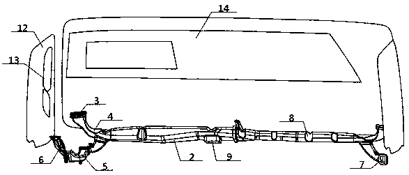
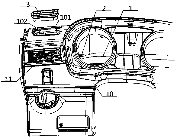
[0047] see Figure 1 to Figure 4 , an air outlet duct system for side window defrosting, comprising a defrosting air duct 2 and defrosting air ducts 3 arranged at both ends thereof, and the middle part of the defrosting air duct 2 communicates with an air-conditioning air inlet 9; The frost air duct 2 is arranged in the dashboard 10 of the cab, and below the defrosting air duct 2 is a face blowing air duct 1 separated from each other. The defrosting air outlets 3 are separated from each other, and the defrosting air outlets 3 are arranged near the cab side window 12 . Preferably, the face air outlet 11 is located below the defroster air outlet 3 .

Embodiment 2

[0049] Basic content is the same as embodiment 1, the difference is:

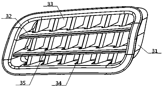
[0050] The outer circumference of the defrosting air outlet 3 is engaged with the inner groove cavity 102 of the air outlet groove 101 , and the air outlet groove 101 is arranged in the dashboard 10 of the cab. The defrosting tuyere 3 includes an outer seat 31 of the tuyere and a fixed plate 32 and a guide plate 33 arranged inside thereof. The outer circumference of the outer seat 31 of the tuyere is inserted into the inner groove cavity 102 of the air outlet groove 101, and the fixed The quantity of the plate 32 is at least one, and the quantity of the guide plate 33 is at least two; The upper and lower inner walls of the outer seat 31 are rotatably connected, and the middle part of the guide plate 33 is rotatably connected with the middle part of the fixing plate 32 . Preferably, the upper and lower inner walls of the outer seat 31 of the tuyere are provided with an outer seat arc groove 34, and the oute...

Embodiment 3

[0052] Basic content is the same as embodiment 1, the difference is:

[0053] The two ends of the defrosting air duct 2 are respectively connected to the bottom of the upward turning air duct 4, and the top of the upward turning air duct 4 is connected to the bottom of the defrosting tuyere 3, and the defrosting air duct 2 is close to the top. The part where the turning-out air duct 4 is connected to the inner end of the side-extending air duct 5, and the outer end of the side-extending air duct 5 is connected to the door defrosting opening 7, and the door defrosting opening 7 is close to the cab side window 12 set up. Preferably, the outer end of the side-extending air duct 5 is connected with the bottom end of the upturn door air duct 6, and the top end of the upturn door air duct 6 is connected with the door defrosting opening 7, and the defrosting tuyere 3, the door defrosting The air outlet directions of the ports 7 are all towards the side window glass 13 .


PUM


Abstract

The invention provides a tuyere duct system used for side window defrosting. The system comprises a defrosting duct, a defrosting tuyere and a car door defrosting port, wherein the defrosting duct isformed in a cab dashboard, the two ends of the defrosting duct is communicated with the defrosting tuyere through an upper turning duct, face blowing ducts which are partitioned from one another are arranged under the defrosting duct, output ends of the face blowing ducts are communicated with a face blowing tuyere, the face blowing tuyere is partitioned from the defrosting tuyere, the defrostingtuyere is arranged near a side window of a cab, the defrosting tuyere comprises a tuyere outer seat, a fixing plate and a guiding plate, the fixing plate and the guiding plate are arranged in the tuyere outer seat, the portion, close to the upper turning duct, of the defrosting duct is connected with the car door defrosting port through a side stretching duct, and the car door defrosting port is formed close to the side window of the cab. The tuyere duct system used for side window defrosting not only does not interfere other parts and has a better defrosting effect, but also is low in duct arrangement difficulty and cost.

Description

technical field [0001] The invention relates to a car window defrosting device, which belongs to the field of defrosting in the automobile manufacturing industry, in particular to an air outlet air duct system used for defrosting side windows, which is specifically suitable for avoiding mutual interference with other components and improving the defrosting effect . Background technique [0002] Throughout the commercial vehicles of major brands at home and abroad, the defrosting air outlets for side window defrosting are either arranged on the side of the instrument panel or on the door. These existing schemes have complex wind paths, and their defects are as follows: [0003] First of all, it will occupy a lot of space inside the instrument panel, and interfere with other components, such as the face blowing air duct, which increases the difficulty of assembly and increases the cost of the air duct; [0004] Secondly, the defrosting air vent is integrated with the instrum...

Claims


Application Information

Patent Timeline
Patent Type & Authority Applications(China)
IPC IPC(8): B60H1/34B60S1/54B60S1/56
CPCB60H1/3414B60S1/54B60S1/56
Inventor 李兰张昱张阳夏然飞邓广胡美龄付尧
Owner DONGFENG COMML VEHICLE CO LTD
Learn More