Back-to-light module

A backlight module, a direct-type technology, applied in the field of direct-type backlight modules, can solve problems such as reducing the performance of LCD panels

Inactive Publication Date: 2005-03-09
AU OPTRONICS CORP
View PDF1 Cites 9 Cited by
  • Summary
  • Abstract
  • Description
  • Claims
  • Application Information

AI Technical Summary

Problems solved by technology

However, as the size of the LCD becomes larger and larger, the number of support columns 23 also needs to be increased. Therefore, in the support column 23, dark lines are often caused due to the effective transmission of light, which reduces the uniformity of the overall light distribution of the LCD panel 25. Performance

Method used


Image

  • Back-to-light module
  • Back-to-light module
  • Back-to-light module

Examples


Embodiment Construction

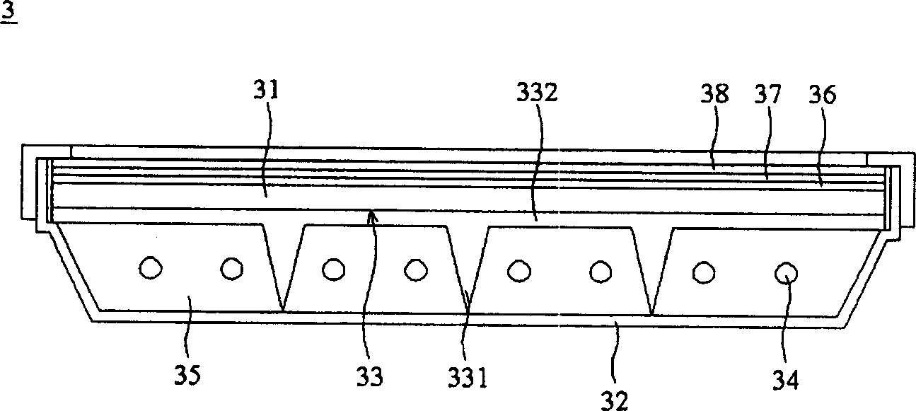
[0014] image 3 It is a cross-sectional view of the first embodiment of the direct type backlight module of the present invention. In this embodiment, the direct type backlight module 3 is connected by a diffuser plate 31 and a reflector plate 32, a cavity 35 is formed between the diffuser plate 31 and the reflector plate 32, and a plurality of light sources 34 are arranged in the cavity 35, In this embodiment, the light source 34 may be a light tube. In order to prevent the diffusion plate 31 from being deformed due to the excessive area of ​​the diffusion plate 31 or the heating of the lamp tube, a light-transmitting support frame 33 is arranged between the diffusion plate 31 and the reflector plate 32 as abutment to prevent the diffusion plate 31 from being deformed.

[0015] In this embodiment, the light-transmitting support frame 33 may be an integral molding structure formed by an injection molding method, and has a plurality of support feet 331 that are commonly connec...


PUM


Abstract

The present invention relates to a downward-vertical type backlight moudle. It includes a scattering plate, a reflecting plate, several light sources and at least one transmission supporting frame placed betwwen the scattering plate and reflecting plate. The reflecting plate is connected on the scattering plate to form a cavity, and the light source is placed in the described cavity, the utilization of the above-mentioned transmission supporting frame can prevent the scattering plate from producing curved deformation.

Description

technical field [0001] The invention relates to a direct-type backlight module, in particular to a direct-type backlight module that can support a diffuser plate to solve the problem that the diffuser plate is deformed by the heat generated by the lighting tube and warped due to insufficient rigidity of the material. Background technique [0002] see figure 1 In the existing direct type backlight module 1 (Japanese Patent No. 5-119703), a support column 13 is arranged below the lighting tube 14 of the direct type backlight module 1 to avoid deformation of the lighting tube 14 . However, the disadvantage of the direct type backlight module 1 is that when the size of the liquid crystal display panel (LCD) (not shown) is larger, the size of the diffusion plate 11 will also be relatively larger, which will cause the diffusion plate 11 to be affected by the lamp tube. The thermal energy emitted by 14 produces a warping deformation phenomenon, thereby affecting the optical proper...

Claims


Application Information

Patent Timeline
Patent Type & Authority Applications(China)
IPC IPC(8): G02B5/02G02F1/13357
Inventor 蔡宜轩周晖凯
Owner AU OPTRONICS CORP
Why Eureka
Try Eureka