Drill pipe transit box of drilling machine

A technology for drill pipes and drilling rigs, which is applied in the field of drill pipe transfer boxes for drilling rigs. It can solve problems such as long loading and unloading cycles, affecting the service life of drill pipes, and collisions between male and female buckles of drilling tools, so as to improve service life, save labor intensity, and avoid bending. deformation effect

Active Publication Date: 2015-01-14
H H DRILL TECH DRILLING MACHINERY CO LTD
View PDF11 Cites 15 Cited by
  • Summary
  • Abstract
  • Description
  • Claims
  • Application Information

AI Technical Summary

Problems solved by technology

[0002] With the development and wide application of domestic coal machinery, mining machinery and non-excavation pipelaying equipment, many units and individuals in China currently have relatively loose management of drilling tools, especially drill pipes, which are randomly placed on the ground or on pipe racks. Due to the long span of the drill pipe, the bending moment is relatively large, and the traction rope is not used when the drilling tools are bundled and left for hoisting, which causes the male and female buckles of the drilling tool to collide with hard objects, and the internal and external thread joints are not separated when loading. Sort by length
Similar bad phenomena occur from time to time, which not only affect the service life of the drill pipe, but also appear to be messy on site
During transfer loading, only a few drill pipes can be hoisted each time or one drill pipe can be lifted by manpower at a time. The loading and unloading period is long, the efficiency is low, and the labor intensity is high.

Method used


Image

  • Drill pipe transit box of drilling machine
  • Drill pipe transit box of drilling machine
  • Drill pipe transit box of drilling machine

Examples


Embodiment Construction

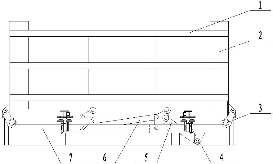
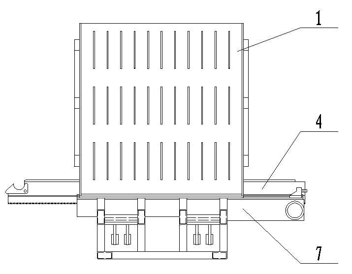
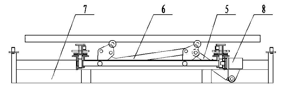
[0017] A drill rod transfer box for a drilling rig, including a box body 1, a number of vertical partitions 2 arranged at equal intervals are symmetrically arranged on the left and right sides of the box body 1, and a space is formed between two adjacent vertical partitions 2. The drill pipe storage room of a row of drill pipes has a base 7 which is detachably mounted on the bottom of the box body 1, and two drill pipe conveying mechanisms 4 for synchronously conveying drill pipes are symmetrically arranged on the base 7, and the drill pipe conveying mechanism 4 includes and The support seat 13 fixedly connected to the base is provided with a slideway arranged along the drill pipe conveying direction on the support seat 13, and a slide seat 9 is installed in the slideway, and the top surfaces of the slide seat 9 of the two drill pipe conveying mechanisms form a The drill pipe support surface, the distance between the drill pipe support surface and the horizontal plane formed by...


PUM


Abstract

The invention provides a drill pipe transit box of a drilling machine. The drill pipe transit box comprises a box body, wherein multiple equidistantly arranged vertical partition boards are symmetrically arranged on the left and right side plates of the box body, a drill pipe storage chamber for holding a column of drill pipes is formed between two adjacent vertical partition boards, a base is installed at the bottom of the box body, drill pipe conveying mechanisms are arranged on the base, each drill pipe conveying mechanism comprises a supporting seat, a slideway is arranged on the supporting seat, and a sliding seat is installed in the slideway; a drill pipe lifting device is arranged between two drill pipe conveying mechanisms. The drill pipe conveying mechanism used for synchronously conveying drill pipes and arranged on the base is used for conveying the drill pipes to the underface of different drill pipe storage chambers in the box body, the drill pipe lifting device arranged between the two drill pipe conveying mechanisms is used for jacking the drill pipes into the drill pipe storage chamber, and the actions are performed in sequence to fill up the drill pipes in the box body, and thus the problem that the drill pipes are placed disorderly on a construction site is solved, the bending deformation of the drill pipes in a placement process is avoided, and the service life of the drill pipes is prolonged.

Description

technical field [0001] The invention relates to an address prospecting device, in particular to a drill pipe transfer box for a drilling rig. Background technique [0002] With the development and wide application of domestic coal machinery, mining machinery and non-excavation pipelaying equipment, many units and individuals in China currently have relatively loose management of drilling tools, especially drill pipes, which are randomly placed on the ground or on pipe racks. Due to the long span of the drill pipe, the bending moment is relatively large, and the traction rope is not used when the drilling tools are bundled and left for hoisting, which causes the male and female buckles of the drilling tool to collide with hard objects, and the internal and external thread joints are not separated when loading. Sort by length. Similar adverse phenomena occur from time to time, which not only affect the service life of the drill pipe, but also appear to be messy on site. Duri...

Claims


Application Information

Patent Timeline
Patent Type & Authority Applications(China)
IPC IPC(8): E21B19/14
CPCE21B19/14
Inventor 王冰陈赤武张荣战宏伟
Owner H H DRILL TECH DRILLING MACHINERY CO LTD
Why Eureka
Try Eureka