Solar charger

A solar charger and control circuit technology, applied in the direction of collectors, secondary battery charging/discharging, electric vehicles, etc., can solve the problems of pollution, waste of resources, and the battery can only be thrown away, so as to achieve convenient use and extended use. effect of life

Inactive Publication Date: 2005-03-09
李龙生
View PDF0 Cites 12 Cited by
  • Summary
  • Abstract
  • Description
  • Claims
  • Application Information

AI Technical Summary

Problems solved by technology

This brings certain convenience to the mobile crowd, but the dry battery can only...

Method used


Image

  • Solar charger
  • Solar charger
  • Solar charger

Examples


Embodiment Construction

[0019] The present invention will be further described below in conjunction with the accompanying drawings and specific embodiments.

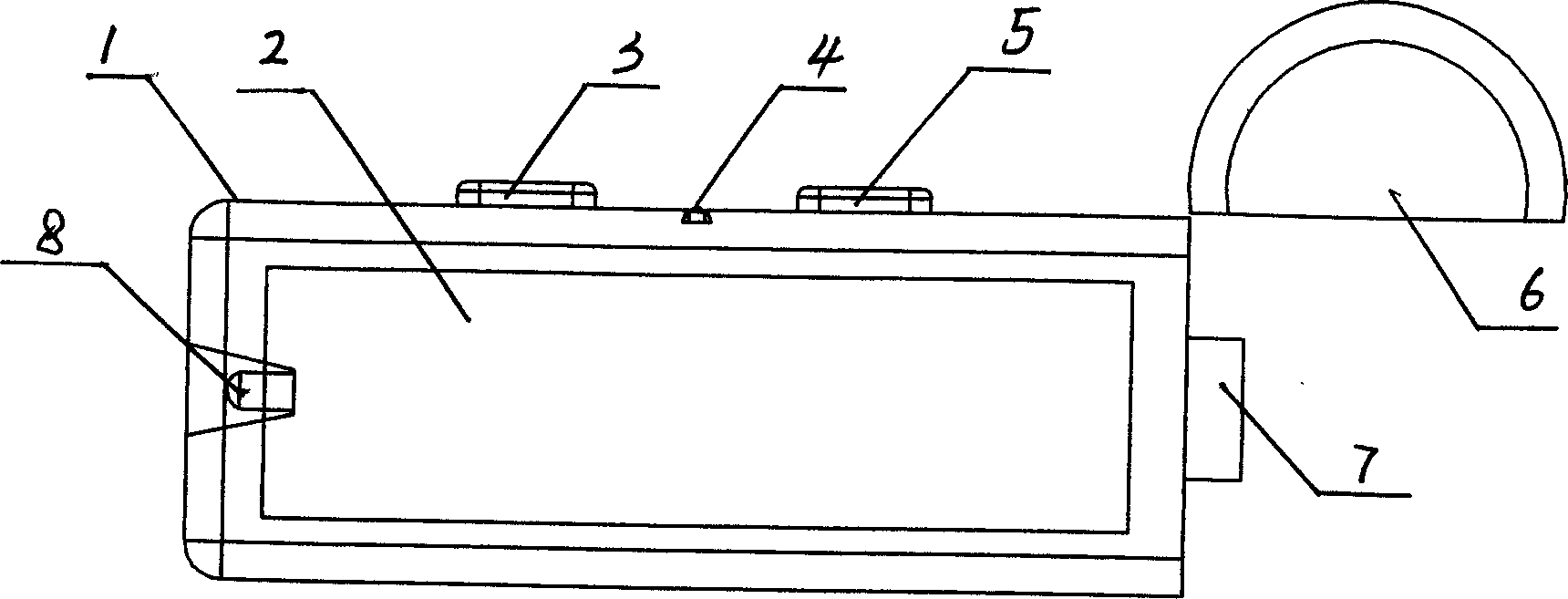
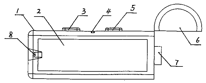
[0020] figure 1 It is a top view of a solar charger, including a charger shell 1, a photovoltaic cell 2 is installed on the top of the shell, a mobile phone plug 7 and a charging indicator light 8 are respectively installed at both ends of the shell, and a The end cover 6, the end cover 6 can be integrated with the shell through a hinge, or can be separated. When not charging, the end cap 6 covers the mobile phone plug 7 for protection. When charging is needed, the end cap 6 is opened and the mobile phone is plugged in to charge. LED 4 and LED switch 3 are installed on the other side of the shell, and when the end cover is integrated with the shell, an end cover switch 5 is also installed.

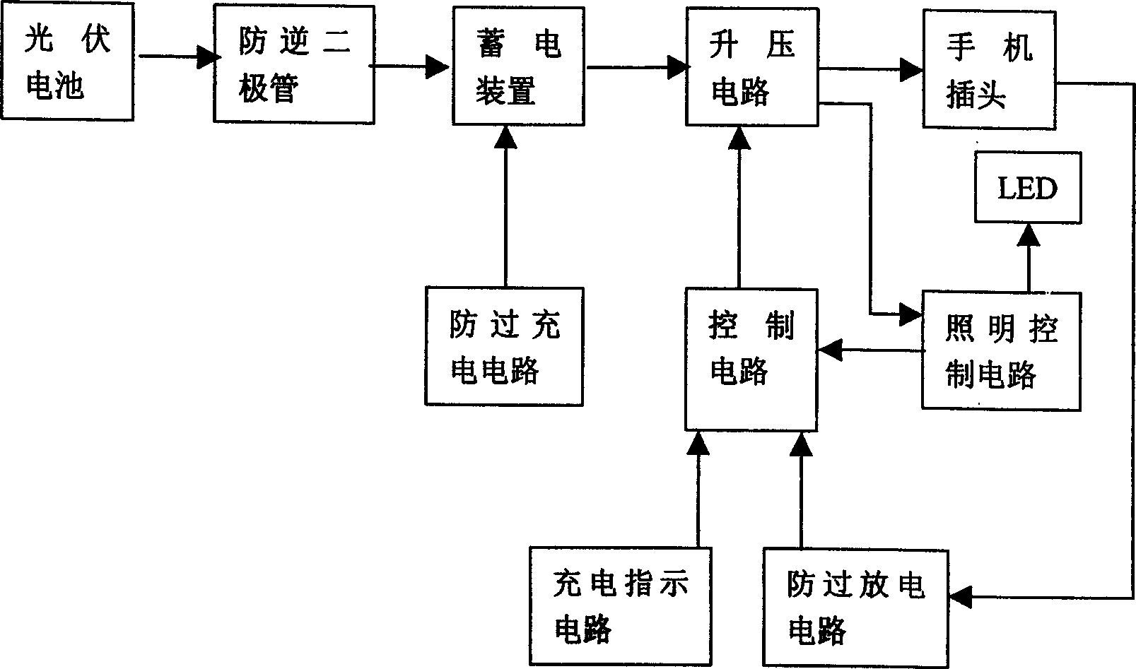
[0021] figure 2 It is the circuit block diagram of the solar charger. The photovoltaic battery is connected to the power storage device through the ant...


PUM


Abstract

This invention discloses a solar charger including a hand call plug, a case with a photovoltaic battery connected with a power storage device by an anti-reverse diode, the said storage device is connected with hand call plug by the voltage boosting circuit. The charger also includes a control circuit, an anti-over-discharge circuit, a charge indicating circuit, an anti-over-charge circuit, an illumination control circuit, a LED and a charge indication lamp.

Description

technical field [0001] The invention relates to a charging device, in particular to a charging device using solar energy. Background technique [0002] With the development of communication technology, the mobile phone market is booming. There is a large market space for mobile phone chargers. Traditional mobile phone chargers use a standard 220-volt AC power supply, and they must be charged in a fixed place with a power supply. For tourists, journalists, drivers and other floating people, their mobile phones often cannot be charged in a timely and effective manner. At present, there is a fast charger in the market that uses dry batteries to quickly collect the energy of the battery into the battery of the mobile phone. This brings certain convenience to the mobile crowd, but the dry battery can only be thrown away after being used once, resulting in waste of resources and environmental pollution. Contents of th...

Claims


Application Information

Patent Timeline
IPC IPC(8): H01M10/44H02J7/00
CPCY02E60/10
Inventor 李龙生
Owner 李龙生
Why Eureka
Try Eureka