Paddy field working machine

A working machine and paddy field technology, applied to the chassis of agricultural machinery, agricultural machinery and machinery, agriculture, etc., can solve the problems of cost increase, easy failure, complex structure, etc., and achieve the effect of cost reduction and easy operation

Inactive Publication Date: 2005-03-16
ISEKI & CO LTD
View PDF2 Cites 4 Cited by
  • Summary
  • Abstract
  • Description
  • Claims
  • Application Information

AI Technical Summary

Problems solved by technology

[0006] The above-mentioned scribe marker driving device drives the left and right scribe markers by respecti

Method used


Image

  • Paddy field working machine
  • Paddy field working machine
  • Paddy field working machine

Examples


Embodiment Construction

[0028] Embodiments of the present invention will be described below with reference to the accompanying drawings.

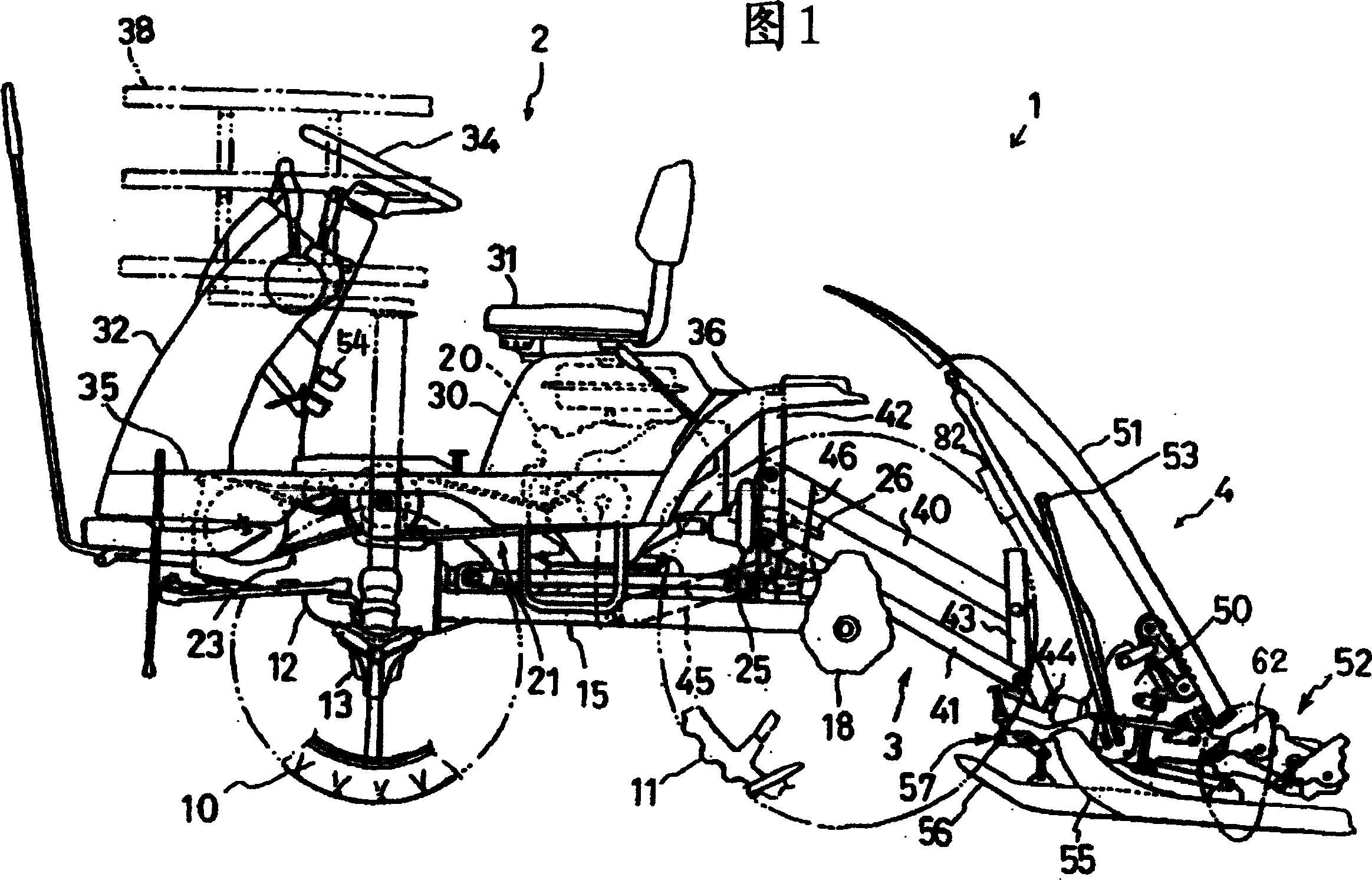
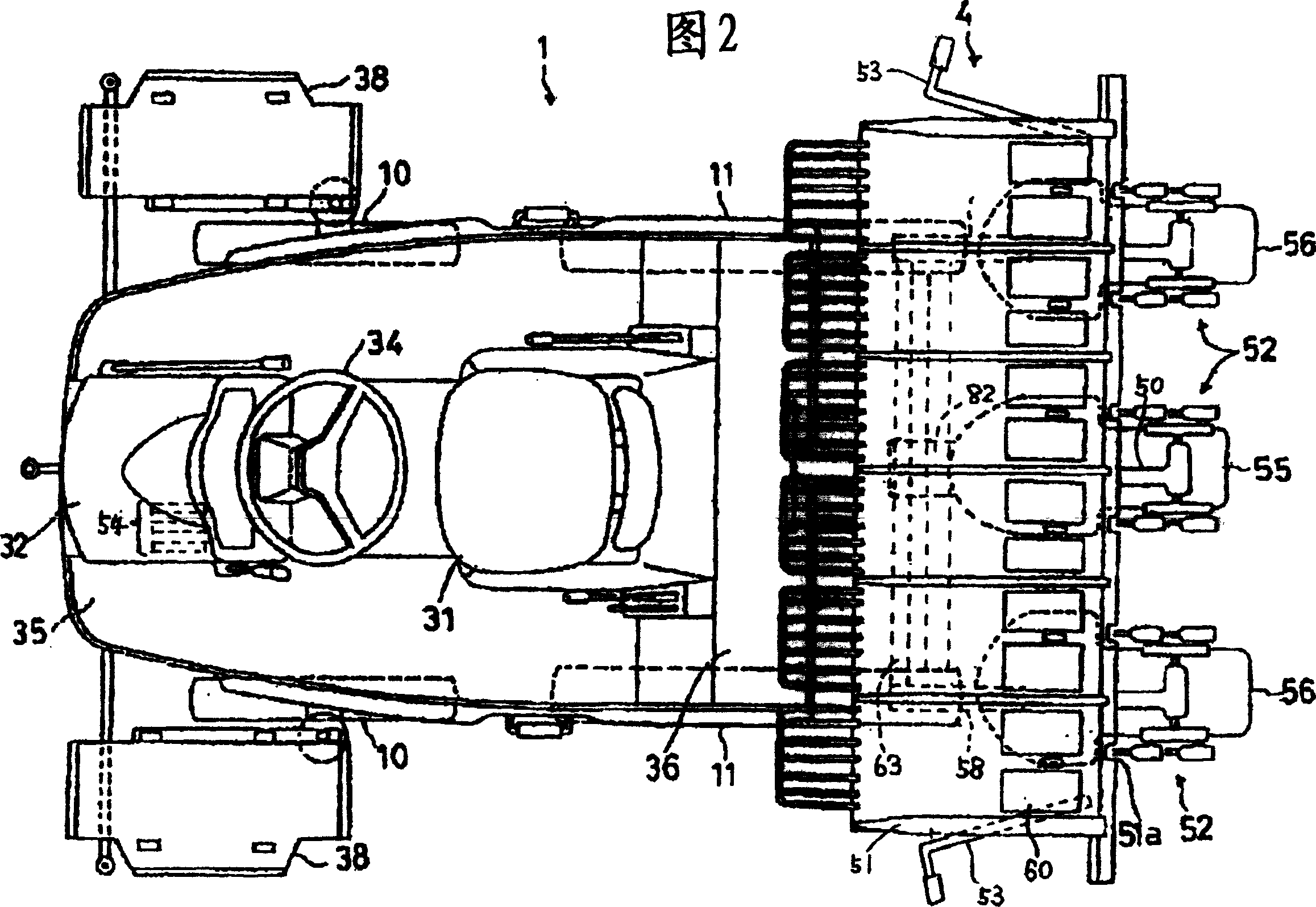
[0029] Fig. 1 and Fig. 2 show a side view and a plan view of a paddy field work machine (rice transplanter) according to this embodiment, respectively.

[0030] The rice transplanter 1 is connected to a rice seedling planting section 4 as a working machine section via a lifting connection device 3 on the rear side of the traveling body 2 . The traveling vehicle body 2 is a four-wheel drive vehicle having a pair of front wheels 10, 10 and rear wheels 11, 11 as driving wheels. Front wheel final transmission boxes 13, 13 are provided, and front wheels 10, 10 are attached to front wheel axles projecting outward from front wheel support portions capable of changing the steering angle of the front wheel final transmission boxes 13, 13. In addition, the front end of the main frame 15 is fixed to the back of the transmission case 12, and the rear wheel gearbox 18 is rota...


PUM


Abstract

In the paddy field working machine, a traveling vehicle body is provided with a farm implement portion and a pair of drawing markers for drawing a line on the surface soil surface at a position at which a traveling vehicle body is passed through in the following step with advance of a farm working part on the right and left sides in advancing direction of the traveling vehicle body and the right and left line-drawing markers as a marker driving device 82 can be operated by an operating linking member of a marker composed of a single motor 85, an L-shaped arm 80, a wire 81, etc., each held in the action position drawing a line on the surface soil surface and in the non-action position not drawing a line.

Description

technical field [0001] The present invention relates to a paddy field operation machine with a marking marker, which marks the advancing route of the fuselage of the next stroke to the surface soil part of the field when performing the return operation. Background technique [0002] In paddy field work machines such as rice transplanters, a pair of left and right line markers are provided, and the left and right pair of line markers can be switched between the state of marking the topsoil surface of the field and the state of not marking the line. A pair of marking markers are installed on the left and right sides of the vehicle body, and the driving device of the marking markers is switched in conjunction with the lifting action of the working machine part. The marking markers are in the marking state, and when the working machine unit is raised to rotate the machine body, the marking markers on the left and right are in the non-drawing state. [0003] The working machine ...

Claims


Application Information

Patent Timeline
IPC IPC(8): A01B69/02A01B51/00A01C11/02
CPCA01B69/022
Inventor 加藤哲十龟治光玉井利男山口信
Owner ISEKI & CO LTD
Why Eureka
Try Eureka