Supercharge Your Innovation With Domain-Expert AI Agents!

Differential amplifier with temp compensation function

A differential amplifier, temperature compensation technology, used in differential amplifiers, amplifiers, amplifiers with semiconductor devices/discharge tubes, etc., can solve problems such as gain and distortion changes

Inactive Publication Date: 2005-03-23
MITSUBISHI ELECTRIC CORP
View PDF0 Cites 3 Cited by
  • Summary
  • Abstract
  • Description
  • Claims
  • Application Information

AI Technical Summary

Problems solved by technology

[0012] In this way, in a differential amplifier without a feedback resistor, there is a problem that the gain and distortion vary depending on the absolute temperature T

Method used


Image

  • Differential amplifier with temp compensation function
  • Differential amplifier with temp compensation function
  • Differential amplifier with temp compensation function

Examples


Embodiment Construction

[0032] Hereinafter, in order to describe the present invention in more detail, the best mode for carrying out the present invention will be described with reference to the accompanying drawings.

[0033] Embodiment 1

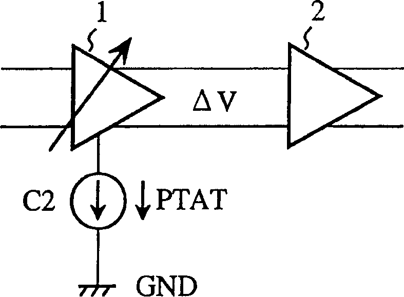
[0034] figure 2 It is a diagram showing the configuration of a differential amplifier with a temperature compensation function according to Embodiment 1 of the present invention. In the figure, 1 is a differential amplifier (the first differential amplifier) ​​with a feedback resistor and a characteristic that the gain is proportional to the absolute temperature, and C2 is a current proportional to the temperature PTAT (Proportionality ToAbsolute Temperature, which is proportional to the absolute temperature) ) constant current source. 2 is a differential amplifier (second differential amplifier) ​​connected to the subsequent stage of the differential amplifier 1, having no feedback resistor and having a characteristic that the gain is inversely proportional ...


PUM


Abstract

A different amplifier with temp. compensation function includes two differential amplifiers, one is with feedback resistance, and gain and direct proportion with temp. the other is connected with the back of the first one, and without feedback resistance and reciprocal with temp. The temp. compensation are by gain and distortion of the amplifiers.

Description

technical field [0001] The invention relates to a differential amplifier without a feedback resistor and having a temperature compensation function capable of temperature compensating the gain and distortion of the differential amplifier. Background technique [0002] figure 1 To show the existing differential amplifier circuit diagram without feedback resistors, in the figure, Vcc is the power supply, GND is the ground, RL is the load resistor, Q1 and Q2 are transistors, and C1 is the constant current source [0003] The operation thereof will be described below. [0004] The differential input current ΔI can be represented by the following equation (1). [0005] ΔI=I0·tanh(ΔV / 2V T ) (1) [0006] In the formula, I0 is the current of constant current source C1, ΔV is the differential input voltage, V T =kT / g, k is Boltzmann's constant, T is absolute temperature, and q is electric charge. [0007] If the above formula (1) is expanded as a series, the f...

Claims


Application Information

Patent Timeline
IPC IPC(8): H03F1/30H03F3/45
CPCH03F1/302H03F3/45085H03F2203/45362H03F2203/45456H03F1/30H03F3/45
Inventor 上田哲也高桥贵纪
Owner MITSUBISHI ELECTRIC CORP
Features
  • R&D
  • Intellectual Property
  • Life Sciences
  • Materials
  • Tech Scout
  • Unparalleled Data Quality
  • Higher Quality Content
  • 60% Fewer Hallucinations
Learn More