
System and device for reducing signal interference in patient monitoring systems

Inactive Publication Date: 2005-03-22
CADWELL INDS
View PDF29 Cites 93 Cited by
  • Summary
  • Abstract
  • Description
  • Claims
  • Application Information

AI Technical Summary

Benefits of technology

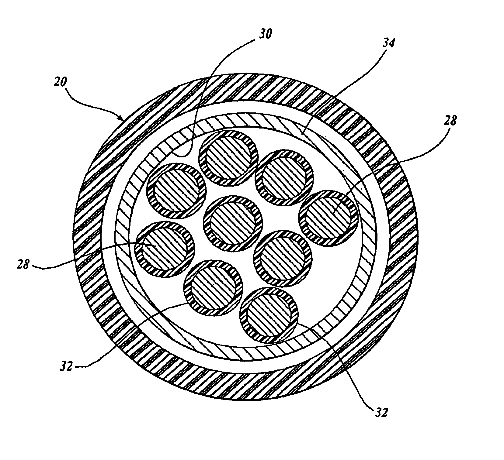
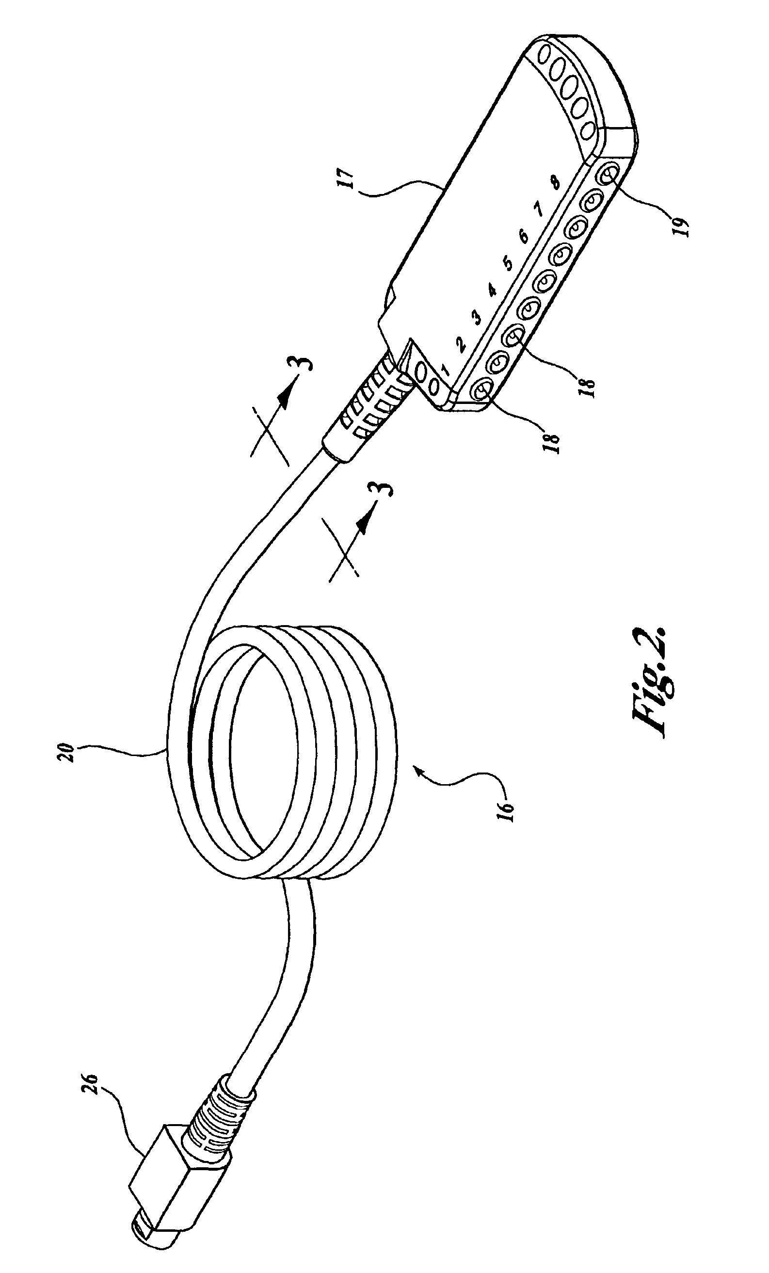
In accordance with a further aspect of the present invention, a system for mitigating signal interference associated with a patient monitoring system is provided. The system includes an input extender that includes a terminal block having a plurality of terminals operable to electrically couple with a plurality of patient electrodes. The terminal block further includes a connector operable to electrically couple with a cable assembly having a plurality of conductive signal wires corresponding to the plurality of patient electrodes encased within a ferrous braided shield.

Problems solved by technology

Accordingly, the low amplitude signals are highly susceptible to interference from environmental electrical / magnetic sources to the extent that the ability for the monitoring system to function properly is affected.
One skilled in the relevant art will appreciate that neurophysiological monitoring in surgical environments can present significant amounts of environmental interference.
Generally described, a typical surgical environment can generate an electrically hostile environment due to the wide variety of electrical devices present in the surgical environment and their relative proximity to the patient and electrode wires.
Additionally, hospital sterility regulations often require that some monitoring devices be outside of the direct surgical environment, thereby requiring a long set of electrode wires.
Additionally, long length wires can also be more susceptible to environmental electromagnetic interference.
Although copper shielding may reduce some portion of electrical interference, a copper braided shield is generally ineffective against magnetic interference.
More specifically, in a surgical environment, copper shielding is generally ineffective in reducing magnetic interference caused by cathode ray tube (“CRT”) displays, drills, cutters, microscope lights, blood warmers, and anesthesia machines.
However, because a CMRR is finite, the effectiveness of a differential amplifier may be reduced for lower amplitude signals, such as physiological signals, especially for environments, such as a surgical environment, that experience higher amounts of interference.
Thus, in surgical environments, the use of differential amplifiers alone is generally ineffective in mitigating the effects of electrical interference upon the physiological signals.
Generally described, the effectiveness of the twisting of two wires can be limited to reducing interference in environments in which an essentially uniform magnetic field strength is present.
For example, in a surgical environment, magnetic interference may be caused by a near-field source that generates a non-uniform field from twist to twist.
Additionally, if the spatial geometry of the twists is not uniform throughout the entire cable, the effectiveness is further reduced.
Referring again to a surgical environment, the spatial geometry of the wires is often at issue because of the often great lengths of wire required.
Thus, twisting signal wires is not sufficient to adequately mitigate interference associated with physiological monitoring.
Although a shield including a ferrous hose can reduce low frequency magnetic interference, the application of a ferrous hose shielded cable can become impractical in several environments.
Referring again to a surgical environment, ferrous metal hose shielded cables are generally not suited to be handled and easily manipulated, as they are bulky, semi-rigid, and weighty.
Moreover, a ferrous hose shielded cable is not well suited for standard mass production cable manufacturing techniques by requiring the addition of insulation to the outside of the hose.
Accordingly, this increases the overall cost of monitoring systems.

Method used


Image

  • System and device for reducing signal interference in patient monitoring systems
  • System and device for reducing signal interference in patient monitoring systems
  • System and device for reducing signal interference in patient monitoring systems

Examples


Embodiment Construction

The present invention is directed to a system and device for mitigating environmental electrical interference. More specifically, in an embodiment of the present invention, a system and device for mitigating environmental interference associated with neurophysiological monitoring in a surgical environment are provided. One skilled in the art will appreciate that the disclosed embodiments are illustrative in nature and should not be construed as limiting.

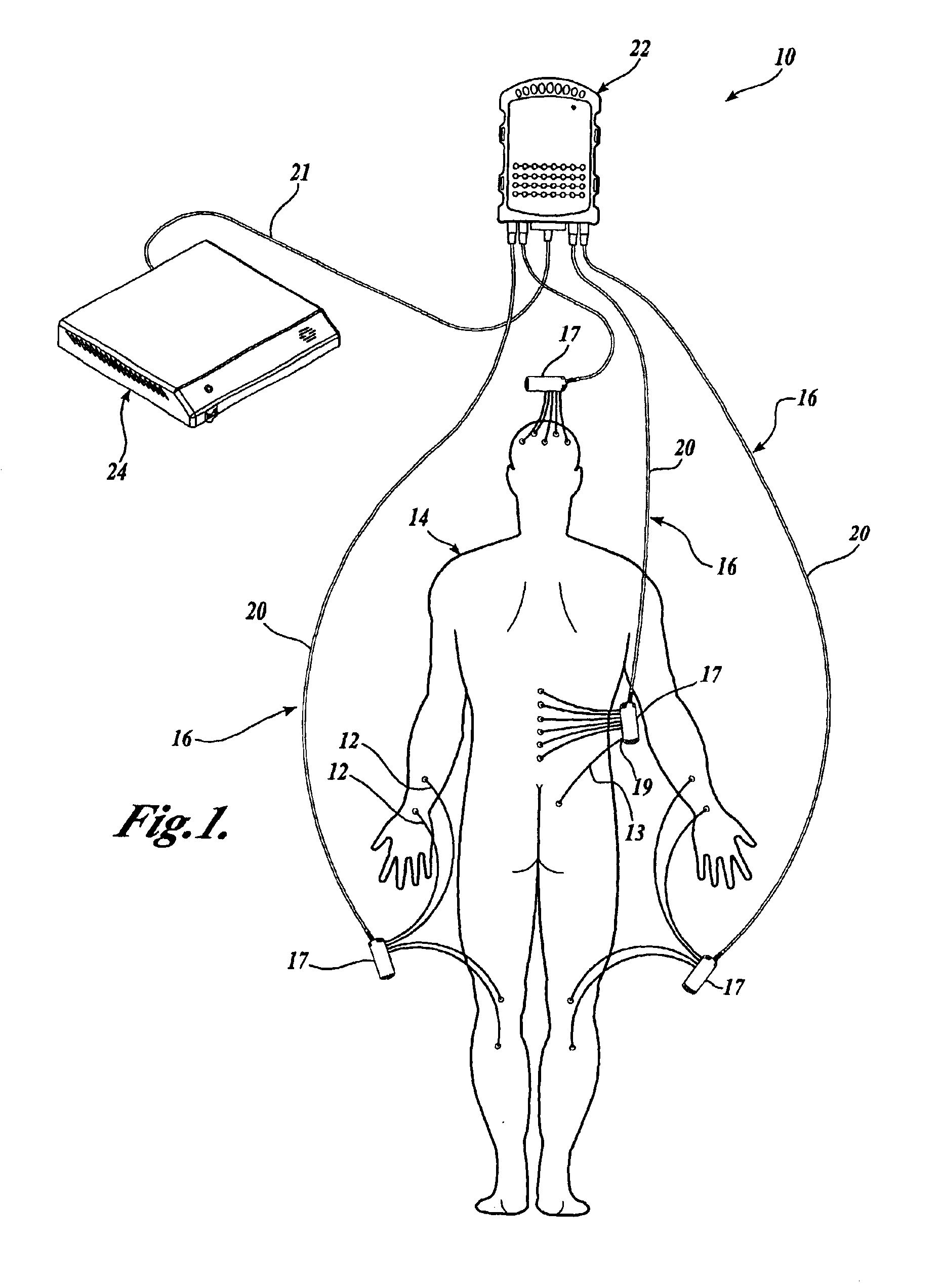
FIG. 1 is a diagram illustrative of a representative embodiment of a neurophysiological patient monitoring system 10 formed in accordance with the present invention. As illustrated in FIG. 1, one or more pairs of electrodes 12 may be connected to a patient 14. The location and placement of the electrodes 12 will coincide with the particular type of monitoring desired, such as neurological monitoring. For example, the electrodes 12 may be connected to the patient 14 to monitor brain wave activity, electric muscle activity, electric he...


PUM

PropertyMeasurementUnit
Electrical conductivityaaaaaaaaaa
Interferenceaaaaaaaaaa
Electrical conductoraaaaaaaaaa

Abstract

A system and device for mitigating interference in patient physiological monitoring is provided, particularly in surgical environments. One or more sets of electrodes are placed on a patient's body and connected to corresponding terminals of an input extender. The terminals of the input extender are connected to a set of signal wires encased by a ferrous shielded cable. The ferrous shielded cable connects to a signal processing unit, which includes a differential amplifier and an active drive topology to drive the shield with a common mode signal. The signal processing unit connects to physiological monitoring equipment.

Description

FIELD OF THE INVENTIONIn general, the present invention relates to patient monitoring systems, and in particular, to a system and device for reducing electrical interference associated with patient monitoring systems.BACKGROUND OF THE INVENTIONIn a typical neurological monitoring environment, one or more sets of electrodes are attached to a patient's body. In turn, the electrodes are electrically connected to one or more pieces of monitoring equipment through signal wires. Depending on the placement of the electrodes, the monitoring equipment can be utilized to monitor various physiological signals to conduct patient tests, such as an electrocardiogram (“ECG”), an electroencephalogram (“EEG”), an electromyogram (“EMG”), and the like. Often, the physiological signals obtained from a patient may be of a low amplitude. For example, a typical physiological signal may have an amplitude as small as 0.2 μV. Accordingly, the low amplitude signals are highly susceptible to interference from ...

Claims


Application Information

Patent Timeline
IPC IPC(8): A61B5/04
CPCA61B5/04A61B2562/222A61B2562/182A61B5/24A61B5/7203
Inventor VILLARREAL, RICHARD A.
Owner CADWELL INDS
Learn More