
Method for measuring currents in a motor controller and motor controller using such method

a technology of motor controller and current measurement method, which is applied in the direction of instruments, transmission systems, analog-digital converters, etc., can solve the problems of unfavorable first method, and achieve the effect of simple and independent gain adjustment for protection and control and enhancement of snr

Inactive Publication Date: 2005-09-01
DANFOSS DRIVES
View PDF17 Cites 101 Cited by
  • Summary
  • Abstract
  • Description
  • Claims
  • Application Information

AI Technical Summary

Benefits of technology

[0012] It should be emphasized that the above sampling method is especially applicable for current sensors on the output phases of the motor controller. The goal being to attenuate random noise by oversampling and averaging, to remove the PWM current ripple of an output phase current, to remove effects from cable ringing and to extract a value for the fundamental output phase current within a switching period referred to the centre line (or start, second average) of the same switching period by loading the control unit to the fullest. Compared to the current in the intermediate circuit, the current on the motor phases is continuous which gives the possibility of applying a very high sampling frequency thus providing much data. With a large amount of data available, it is possible to skip data and still have enough data available to achieve symmetry with respect to the centre line of a switching period.
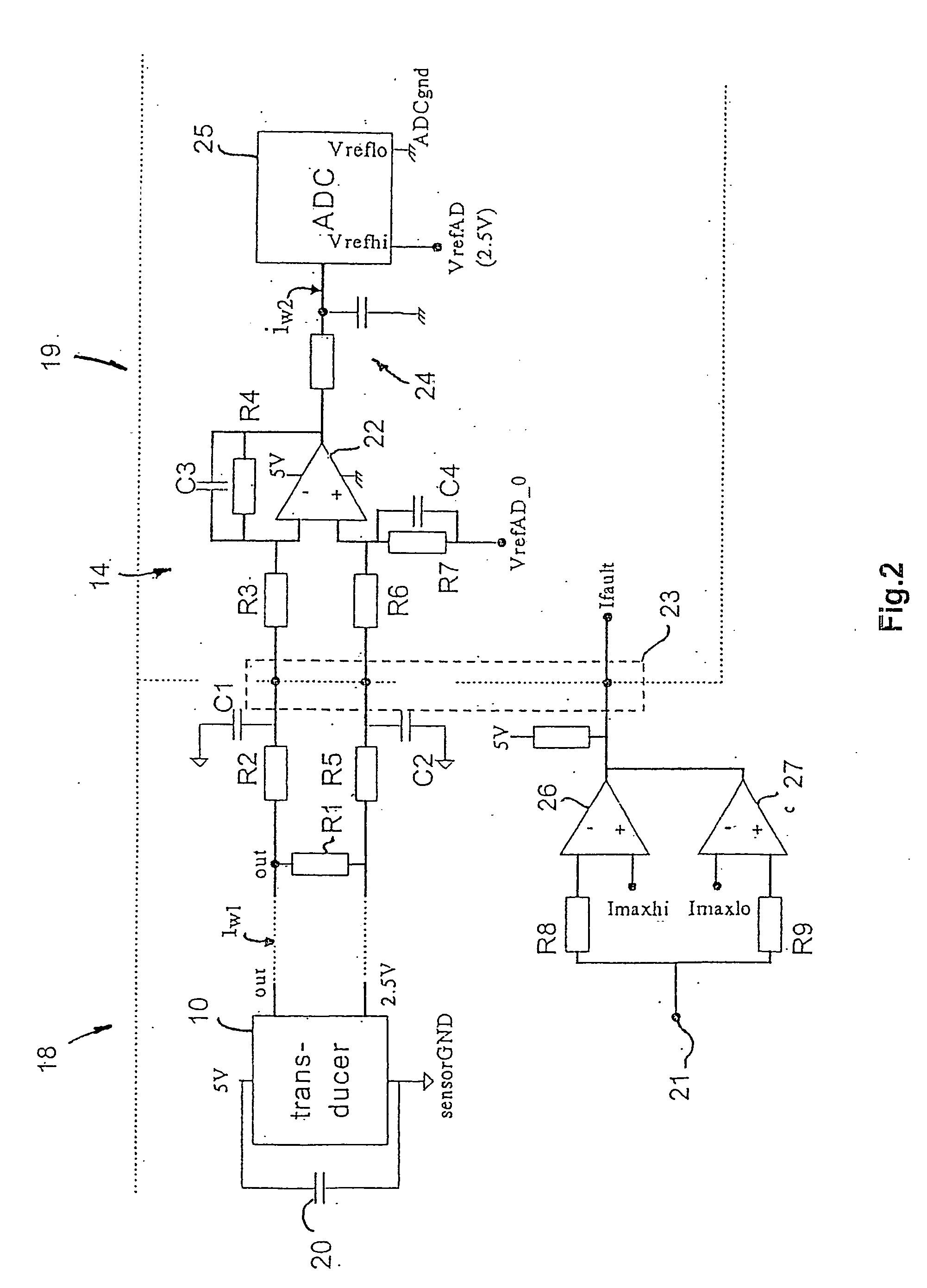
[0024] Placing a filter on the power card in the signal path of the current sensing device makes it possible to control the analog filtering degree independent of an internal bandwith of the current sensing device. Such filter may be a lowpass filter having a suitable cut-off frequency.

Problems solved by technology

The first method is not very useful since an evenly distributed sampling over the switching period is omitted.

Method used


Image

  • Method for measuring currents in a motor controller and motor controller using such method
  • Method for measuring currents in a motor controller and motor controller using such method
  • Method for measuring currents in a motor controller and motor controller using such method

Examples


Embodiment Construction

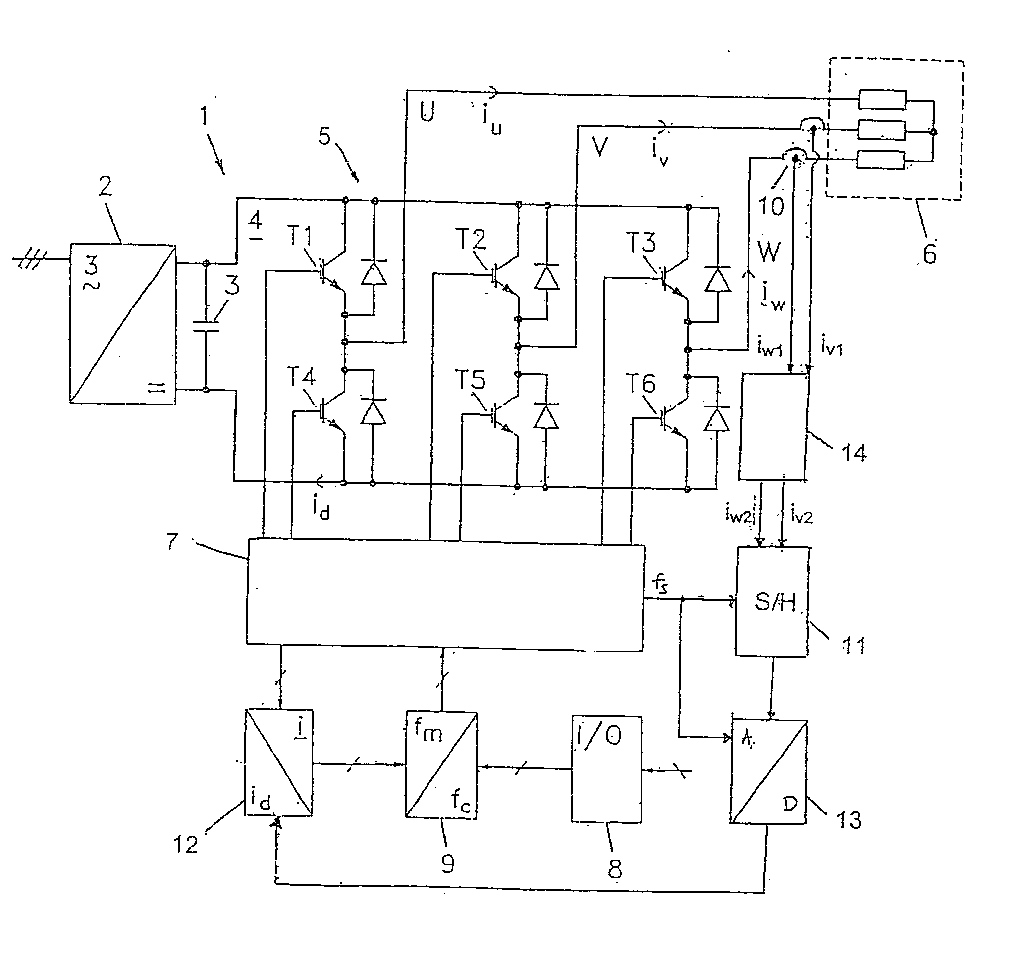
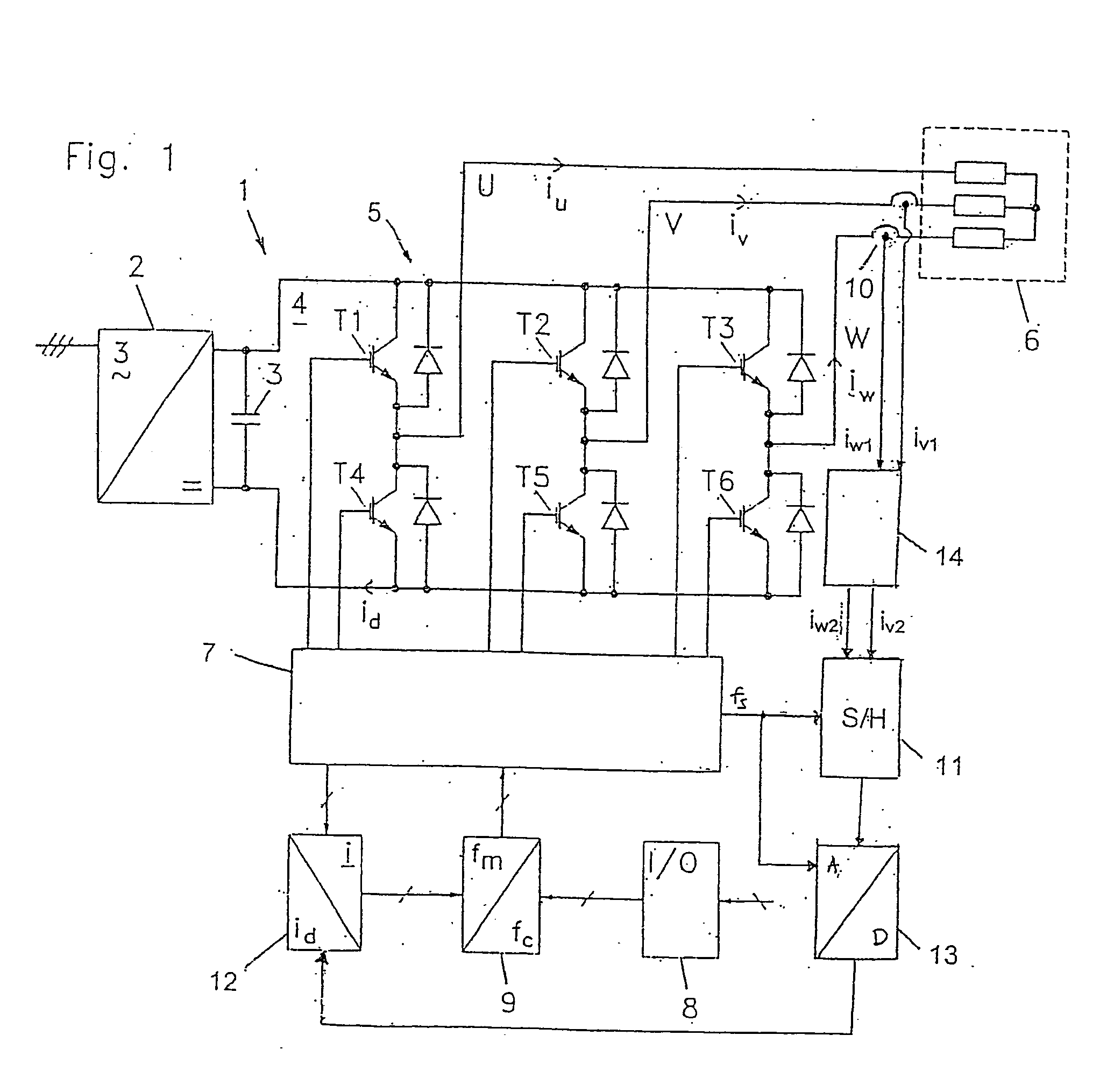
[0039] A frequency converter 1 shown in FIG. 1 consists of an uncontrolled rectifier 2 with intermediate circuit capacitor 3, which feeds a DC intermediate circuit 4 with an inverter bridge 5. The inverter bridge consists of controlled semiconductor switches T1, T2, T3, T4, T5 and T6, which by pulse width modulation transform the direct voltage of the intermediate circuit into a 3-phase alternating voltage on the output or phase conductors U, V, and W. In the embodiment shown, the semiconductor switches are transistors of the IGBT type (Insulated Gate Bipolar Transistor). As usual, freewheeling diodes are coupled in antiparallel with the transistors. The 3-phase output voltage U, V, W of the inverter is supplied to a load 6 in the form of a three-phase asynchronous motor.

[0040] The inverter bridge is controlled by a control circuit 7, which includes a pulse width modulator and a driver circuit for control of the transistors. For operation of the motor controller, this is provided w...


PUM


Abstract

The invention relates to a method for measuring currents in a motor controller. Some current sensing devices placed on the motor wires or inside the motor controller provide low amplitude output signals thus complicating sampling and data processing. In order to improve the signal / noise ratio, an oversampling technique is disclosed which makes used of a differential transmission of the output signal. Further, by applying intelligent sorting techniques on the sampled data, a substantial improvement in the signal / noise ratio can be obtained. The invention also concerns a motor controller using this method, and discloses the use of a power card and a control card, where the current sensing device is placed on the power card and a differential amplifier is placed on the control card. The gain of the differential amplifier is controlled by components placed on the power card as well as on the control card.

Description

CROSS-REFERENCE TO RELATED APPLICATIONS [0001] This application is entitled to the benefit of and incorporates by reference essential subject matter disclosed in International Application No. PCT / DK03 / 00243 filed on Apr. 11, 2003 and Danish Patent Application-No. PA—200200572 filed on Apr. 17, 2002.FIELD OF THE INVENTION [0002] The invention concerns a method for measuring currents in a motor controller and a motor controller using this method. By way of example such motor controllers are frequency converters or servo drives. BACKGROUND OF THE INVENTION [0003] A standard PWM (pulse-width-modulation) motor controller normally includes a control card and a power card. The control card is typically a power invariant unit which is used over the power range of a motor controller series. The power card is by nature a function of the power size meaning that variance in a converter series should be placed here. The control card includes the digital processing unit for controlling the conver...

Claims


Application Information

Patent Timeline
IPC IPC(8): H02P7/29
CPCH02P7/29
Inventor ANDERSEN, HENRIK ROSENDAL
Owner DANFOSS DRIVES
Learn More