Side channel compressor

A compressor and side channel technology, applied in mechanical equipment, machines/engines, liquid fuel engines, etc., can solve the problems of complex and expensive manufacturing of shell and half shells

Inactive Publication Date: 2005-03-30
M.米勒电气有限责任公司
View PDF1 Cites 9 Cited by
  • Summary
  • Abstract
  • Description
  • Claims
  • Application Information

AI Technical Summary

Problems solved by technology

[0003] The manufacture of two different casing half-shells is complex and expensive, one of which forms the actual casing with its support point for the impeller and the other the cover

Method used


Image

  • Side channel compressor
  • Side channel compressor
  • Side channel compressor

Examples


Embodiment Construction

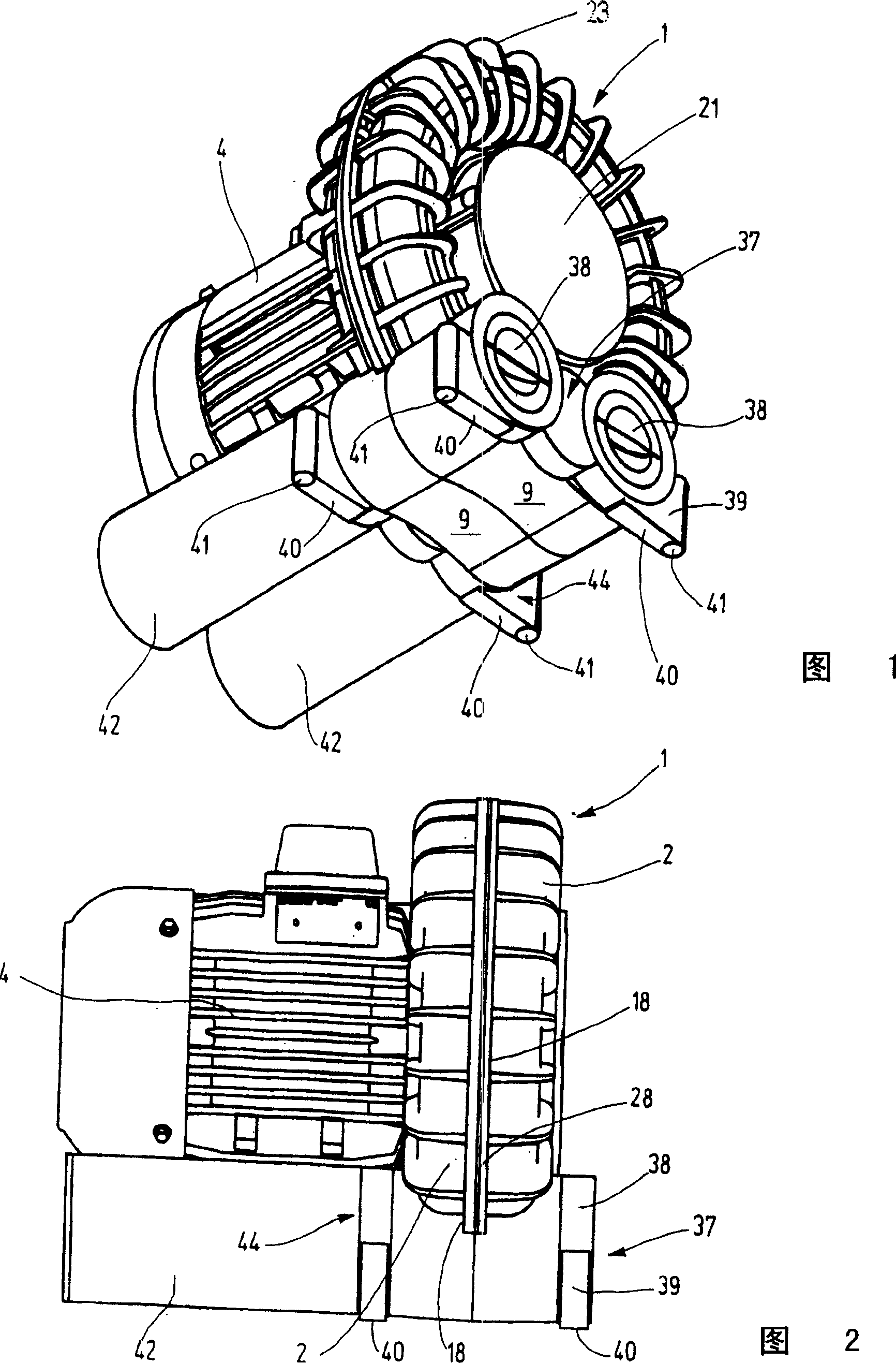
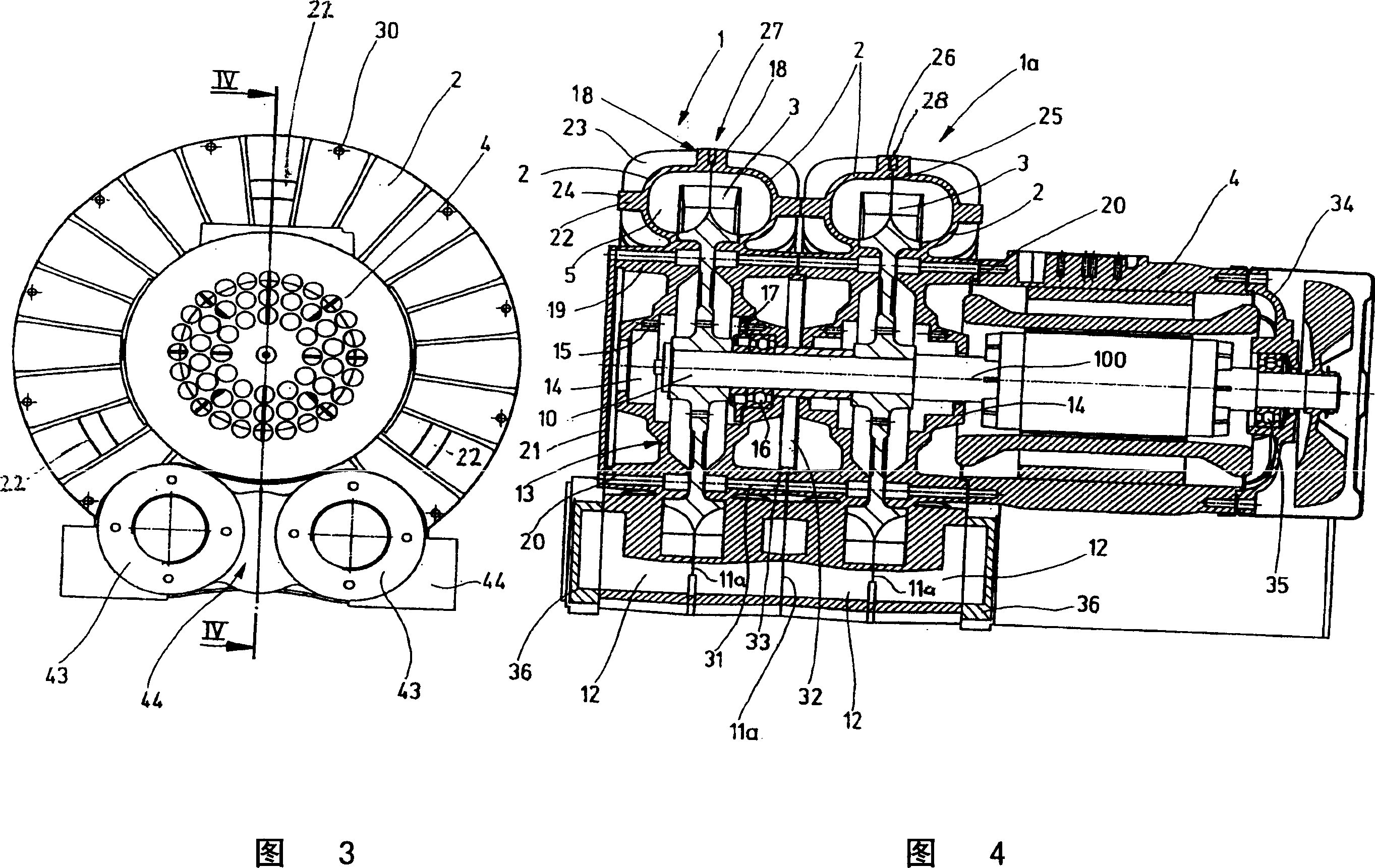
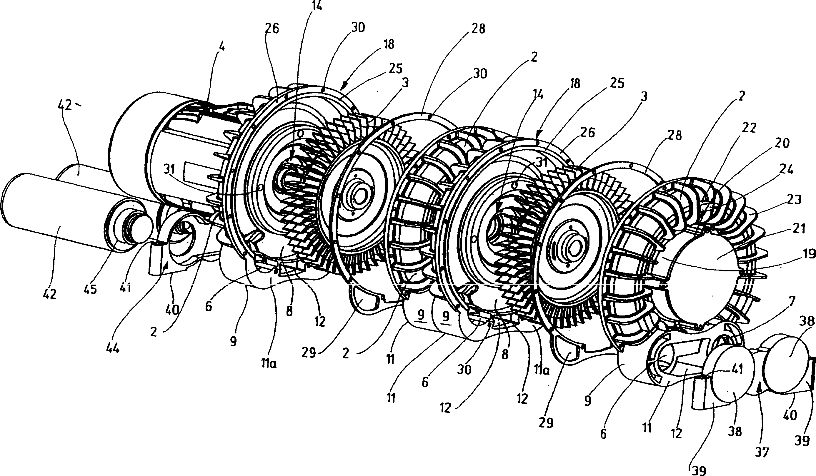
[0020] The side-channel compressor shown in FIGS. 1 and 2 has an essentially annular impeller housing 1 , which consists of two identical housing half-shells 2 and encloses an impeller, designated 3 in FIG. 4 . The impeller 3 is driven by an electric motor 4 which is coaxially flanged to the impeller housing 1 on one side. The two housing half-shells 2 forming the impeller housing 1 are identical. Each housing half-shell 2 has an impeller-accommodating side channel 5 which extends over a large part of the circumference and connects a shaped air intake duct 6 with a shaped air outlet duct 7 . Between the air intake line 6 and the air discharge line 7, a shut-off piece 8 is arranged, as is known per se for side-channel compressors. The air intake pipe 6 and the air discharge pipe 7 are in a common housing part 9 which is integrally formed on the housing half-shell 3 and has a flat mating surface 11 or 11 a extending perpendicularly to the impeller axis 10 on both sides. In the...


PUM


Abstract

A side channel compressor comprises at least one annular and two semi-shell type housing (1) which encloses a rotary turbine wheel (3) supported therein and is provide with an air intake and an air discharge pipes (6, 7), the housing of the turbine wheel is provided with two same semi-housings (2) joined together at planes (25) via planar separation surfaces at right angles to the rotation axis (10) of the turbine wheel (3), an annular ring (28) is arranged in the plane (25), and the two semi-housings (2) are aligned by the ring.

Description

technical field [0001] The invention relates to a side channel compressor with an annular two-half-shell impeller housing surrounding an impeller rotatably supported therein and having an air intake duct and an air discharge duct. Background technique [0002] A typical example of such a side channel compressor is described in DE 2 223 762 A1. In such side-channel compressors, the impeller housing consists of two housing half-shells of different design, one of which bears a rolling bearing seat of the rolling bearing for supporting the shaft of the impeller and a similarly formed flange for the The motor that drives the impeller is flanged. The other casing half-shell is the cover, which is screwed to the casing half-shell supporting the impeller by means of screws distributed along the edge. On their outer edges, the two housing half-shells are each provided with a flat surface, wherein in the assembled state the flat surfaces abut against a parting surface extending perp...

Claims


Application Information

Patent Timeline
Patent Type & Authority Applications(China)
IPC IPC(8): F04D23/00F04D29/40F04D29/42F04D29/62
CPCF04D23/008F04D29/626F04D29/403F04D29/4226
Inventor R·库恩
Owner M.米勒电气有限责任公司
Why Eureka
Try Eureka