

Spinning machine
A spinning machine and fiber technology, applied to spinning machines, open-end spinning machines, continuous winding spinning machines, etc., can solve the problems of low operating efficiency and difficulty in switching the spinning twist direction, and improve the reliability Operability, quality improvement, and smooth running effect
- Summary
- Abstract
- Description
- Claims
- Application Information
AI Technical Summary
Problems solved by technology
Method used
Image

Examples
Embodiment Construction
[0039] Next, embodiments of the present invention are described. However, the present invention is not limited to the examples. Various changes may be made to the described embodiments without departing from the spirit of the invention.
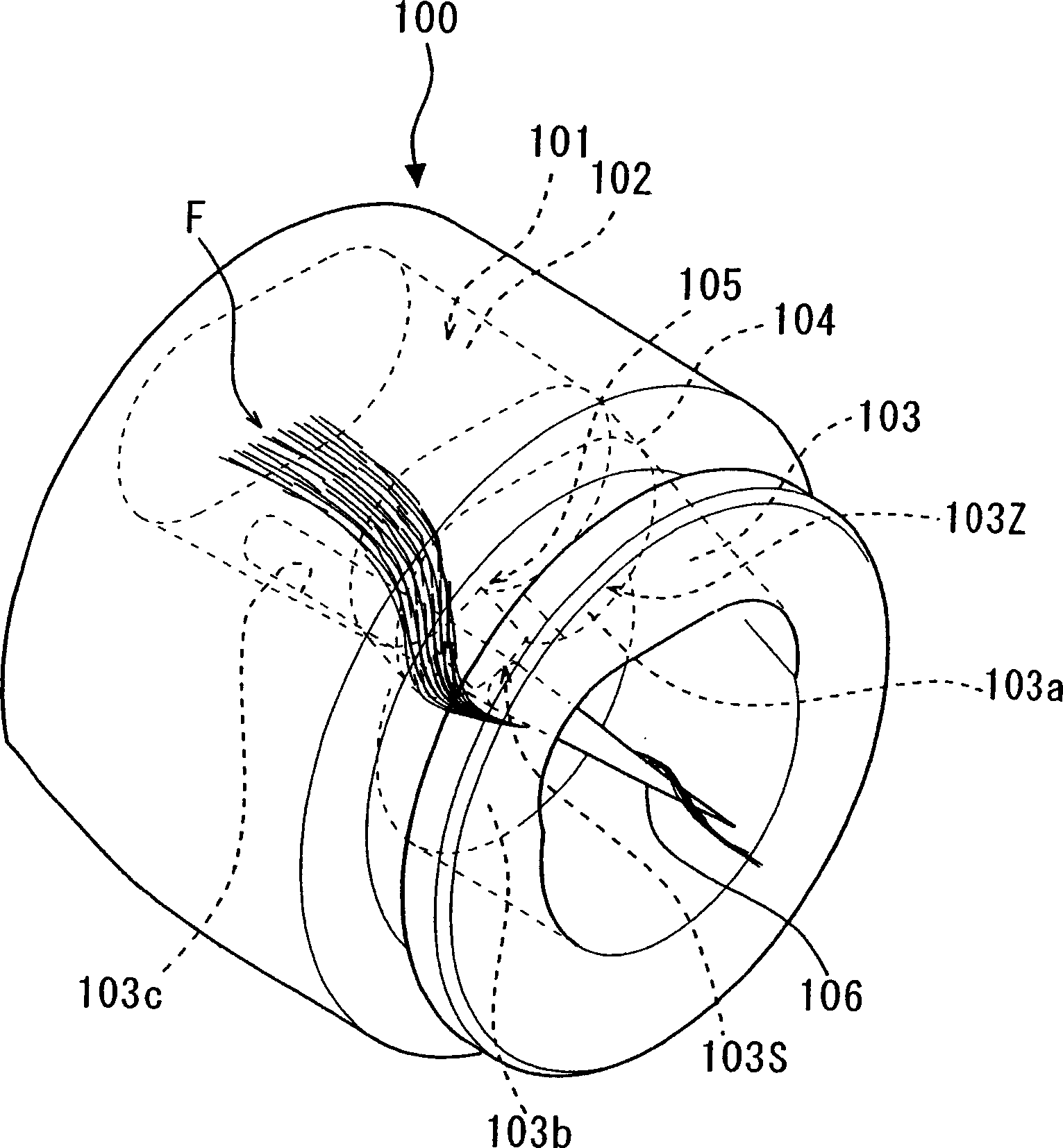
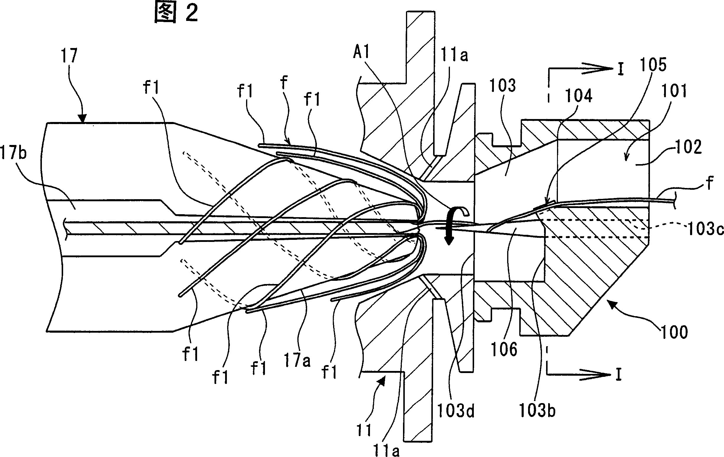
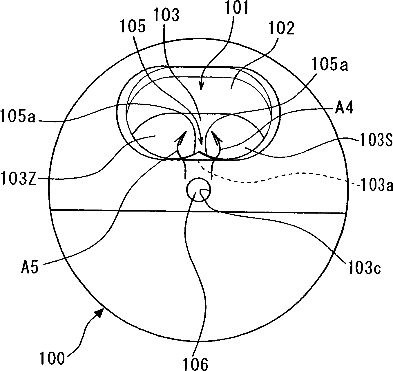
[0040] According to the general structure of spinning machine of the present invention and reference Figure 7 The overall structure of the described spinning machines is the same. Therefore, a detailed description thereof is omitted. Moreover, the present invention is only different from the above-mentioned conventional spinning machine in terms of the structure, operation and effect of the needle holder. Therefore, see below Figure 1-6 The description will focus on the needle holder of the spinning machine according to the present invention.
[0041] The fiber introduction hole 101 is similar to the fiber introduction hole 10a in the needle holder 10 described above, which is also formed in the needle holder 100 according to the presen...
PUM
 Abstract
Description
Claims
Application Information