Goods rack connector

A technology of connectors and racks, which is applied in the direction of furniture connection, connecting components, household appliances, etc., can solve the problems of inconvenient assembly and disassembly, installation restrictions, and complex overall manufacturing of connectors, and achieves the effect of simple connection and extended use range.

Inactive Publication Date: 2005-04-06
李向明
View PDF2 Cites 10 Cited by
  • Summary
  • Abstract
  • Description
  • Claims
  • Application Information

AI Technical Summary

Problems solved by technology

But the above-mentioned structure also has the following disadvantages: a: when encountering multi-layer object racks, its installation will be limited, and the rack bodies at both ends of the rack columns are easier to assemble and disassemble, while the rack bodies located in the middle section are inconvenient to assemble and disassemble ;b: The characteristic of the connection of this structure is that it is locked by the conical surface, and after the storage rack has been used for a period of time, due to the action of gravity, the pillar and the connector of the rack body are in a relatively firm locked state. The fixing sleeve and the fastening sleeve are separated; c: The overall manufacturing of the connector composed of the fixing sleeve and the fastening sleeve is slightly complicated, which will increase the overall manufacturing cost of the shelf

Method used


Image

  • Goods rack connector
  • Goods rack connector
  • Goods rack connector

Examples


Embodiment 1

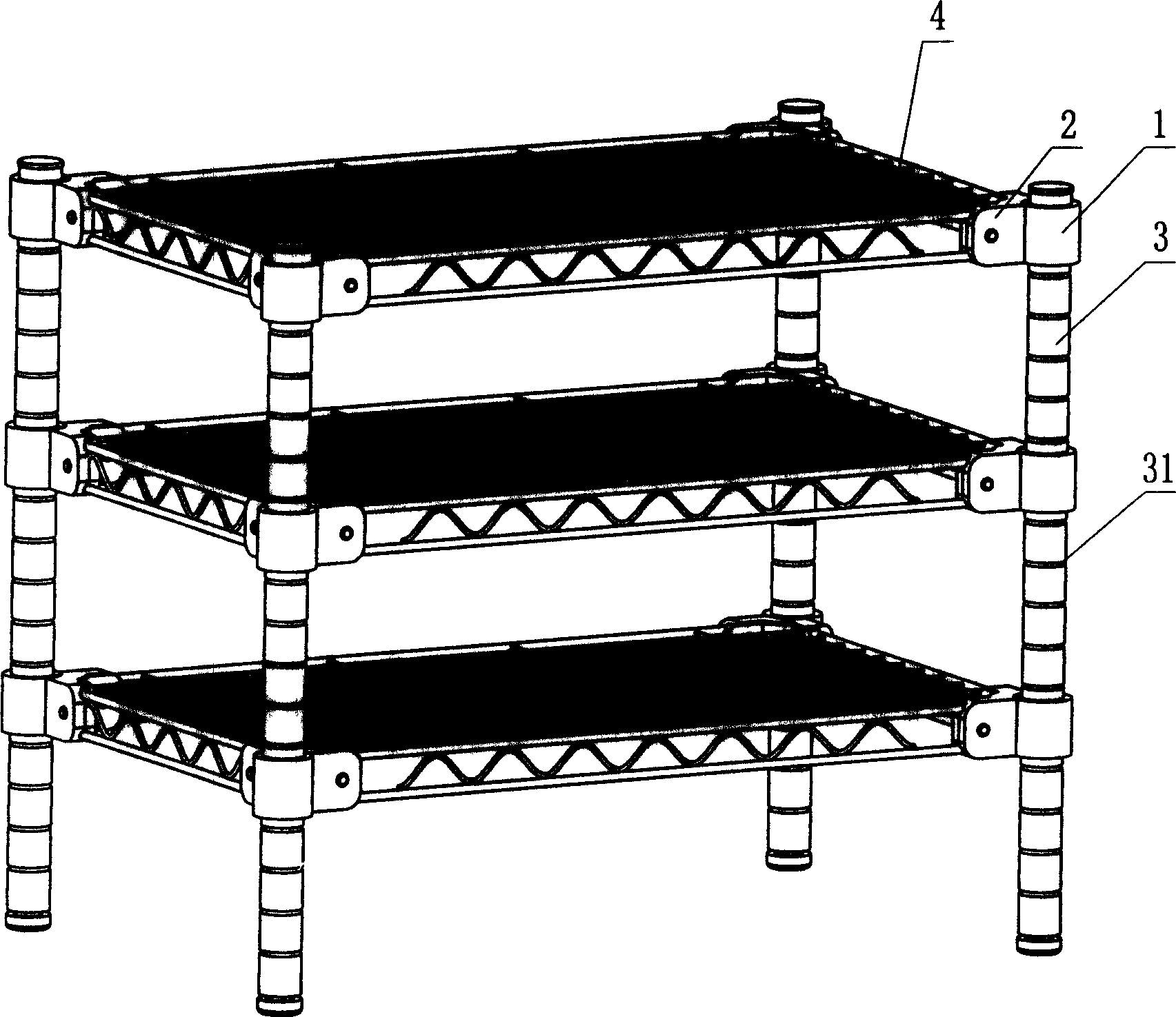
[0025] Embodiment one, multi-layer shelf:

[0026] Such as figure 1 , figure 2 ,image 3, Figure 4 1. For the multi-layer storage rack shown in Figure 5, when the support rod 3 adopts a metal round tube or rod, and the joint part of the rack body 4 and the support rod 3 is a pipe, the locking mechanism described in the above-mentioned connector can be as follows The structural form realizes the locking connection between components.

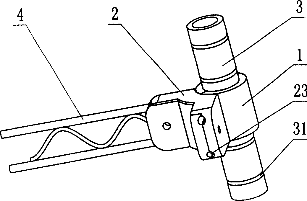
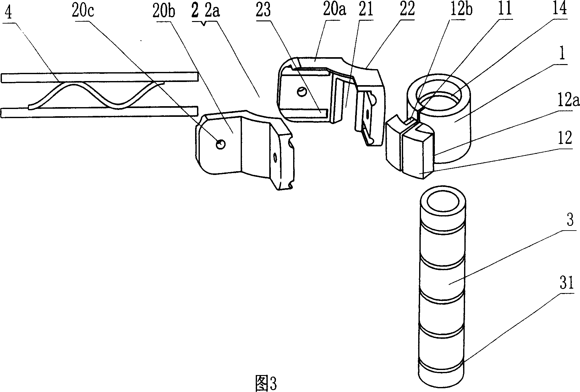
[0027] Near the opening groove 11, a boss 12 is set near the outer edge of the sliding sleeve 1. The top of the above-mentioned boss 12 has a groove communicating with the opening groove 11. Two bosses 12 between the top of the boss 12 and the outer edge of the sliding sleeve 1 The side is provided with an inwardly concave card slot 12a, and an introduction section 12b is provided on the upper part of the card slot 12a;

[0028] The above-mentioned ferrule 2 in the shape of an angular plate is a right-angle corner code 2a, and a bayonet 21 i...

Embodiment 2

[0029] Embodiment two: bracket

[0030] Such as Figure 6 , the bracket shown in Figure 7, when the support rod and a crossbar connector of a pipe rod, the locking mechanism of the above-mentioned connector can be in the following structural form:

[0031] The locking mechanism of the above-mentioned connector includes a sliding sleeve 1 and a rectangular ferrule 2b, wherein a groove communicating with the opening groove 11 is opened on the top of the boss 12, and the boss 12 between the top of the boss 12 and the outer edge of the sliding sleeve 1 Both sides are provided with an inwardly concave card slot 12a, the upper part of the card slot 12a is provided with an introduction section 12b, and one end of the above-mentioned rectangular ferrule 2b is provided with a bayonet 21a, and the width of the bayonet 21a is slightly smaller than that of the boss 12. The width of the card slot 12a, the surface on the side of the bayonet 21a is adapted to the surface of the boss 12, and...

Embodiment 3

[0033] Embodiment three: hanger

[0034] Such as Figure 8 , Figure 9 In the shown hanger, when the supporting rod 3 is connected to the hanging rod 30 with a hook, the locking mechanism of the above-mentioned connector can be in the following structural form: an annular groove 13 is arranged along the outer edge of the sliding sleeve 1, and the annular groove 13 The groove 13 matches the hook body at one end of the hanging rod 30. Specifically, the above ferrule 2 is a hook body provided at one end of the hanging rod. Groove 13 groove bottom diameters, can lock the opening groove 11 of ferrule 2 after the hook body is buckled in like this.

[0035] The shape of the inner cavity of the sliding sleeve 1 in the above three embodiments can be made into a circle, ellipse or triangle according to the shape of the support rod 3, and the material and shape to be used can be determined according to the product design.

[0036]In order to ensure the accurate positioning of the asse...


PUM


Abstract

The device including slides the set and sleeve chuck, states the slippery wrap to be equipped with with the outrigger skids the coordinate cavity, its characteristic is states slides between a set of outflow boundary and the cavity opens has as soon as links up open slot, an above sleeve chuck end and the thing frame body are connected, another end establishes Yu Huatao in the outflow boundary, in sleeve chuck with slides between the set to be equipped with after sleeve chuck the card enters slides a set of outflow boundary to be able to slide a set of institute to suppose open slot to in closed locking organization. The invention because uses above tightens the organization, when assembly, the slippery wrap may facilitate the localization to the outrigger free position, then enters through sleeve chuck the card its locking, also because sleeve chuck an itself end is loaded with the installment position which matches with the thing frame body or sleeve chuck itself is the thing frame body nose, therefore causes an entire thing connection to change extremely simply, but acts according to the different frame body specification design the coupling, may adapt the many kinds of specifications different to set at a thing connection, greatly expanded the coupling applicable scope, provides a kind of new component for a thing production.

Description

technical field [0001] The invention relates to a rack tool, in particular to a connector for a rack. Background technique [0002] In daily life, storage racks composed of various structures, hangers, brackets, etc. The above-mentioned existing problems, Chinese patent CN2503777Y discloses a rack connector, including a support rod, a connector and a rack for storage, the support rod is provided with several positioning grooves at equal intervals along the axial direction, and the connector consists of two arcs The left and right sides of the two are equipped with convex-concave snap-fitting structures, which form a conical tube with a small upper part and a larger lower part after the two sides are interlocked. The sleeve of the grid frame matches the inner diameters at both ends of the sleeve and the conical cylinder. The storage rack with this structure, although the height between the two storage racks can be adjusted according to the needs of use, it is very troubleso...

Claims


Application Information

Patent Timeline
IPC IPC(8): A47B46/00F16B12/00
Inventor 李向明
Owner 李向明
Why Eureka
Try Eureka