Device and method for field calibration of vision measurement system

A technology of visual measurement and measurement system, which is applied in the direction of measuring devices, optical devices, photogrammetry/video metrology, etc. It can solve the problems of inconsistent calibration environment and application environment, complex operation of the calibration process, and high labor intensity. Fast measurement element calibration and system global calibration, strong operability and high efficiency

Inactive Publication Date: 2005-04-13
TIANJIN UNIV
View PDF0 Cites 62 Cited by
  • Summary
  • Abstract
  • Description
  • Claims
  • Application Information

AI Technical Summary

Problems solved by technology

[0003] In the existing measurement system calibration method, the calibration of the measurement elements (camera and sensor) and the global calibration of the system are realized step by step. The calibration process is complex and labor-intensive, and the calibration of the measurement eleme

Method used


Image

  • Device and method for field calibration of vision measurement system
  • Device and method for field calibration of vision measurement system

Examples


Embodiment approach

[0020] Embodiment 1 of field device of visual measurement system:

[0021] The on-site calibration device of the vision measurement system of the present invention includes a space three-dimensional coordinate measurement system and a three-dimensional target. The three-dimensional target is set within the working range of the space three-dimensional coordinate measuring system, and the three-dimensional target is composed of a base plate and precision calibration components arranged on the base plate. The space three-dimensional coordinate measurement system adopts theodolite industrial measurement system. Stereo targets can be used as sensor calibration targets and system measurement targets.

Embodiment 2

[0023] The only difference from the first embodiment of the on-site calibration device for the visual measurement system is that the three-dimensional coordinate measurement system uses a laser tracker.

[0024] In addition to the above-mentioned theodolite industrial measurement system and laser tracker, other spatial three-dimensional coordinate measurement systems can also be selected for the spatial three-dimensional coordinate measurement system of the on-site calibration device of the visual measurement system of the present invention.

Embodiment 1

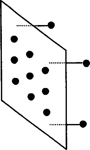
[0026] Such as figure 1 As shown, the precision calibration element in the stereo target is a standard ball, and 12 standard balls are divided into two groups and fixed on both sides of the stereo target substrate. One group consists of 9 standard balls to form a sensor calibration target, and one group consists of 3 standard balls. The theodolite industrial measurement system measures the target, and the three-dimensional target is calibrated under the coordinate measuring machine to obtain the coordinate transformation relationship of the two sets of standard spheres.

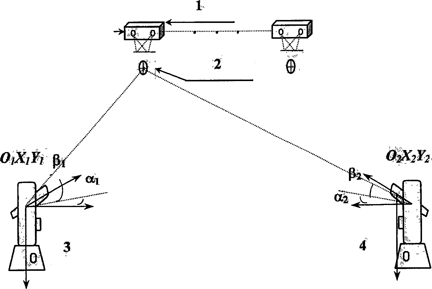
[0027] Such as figure 2 As shown, according to the range of the sensor 1, the calibrated stereo target 2 is installed at the working range of the sensor 1, and two cameras of the sensor 1 are used to collect 9 standard ball images of the sensor calibration target on the stereo target respectively, According to the calibration mathematical model of the camera and the sensor, the calibration parameters of the...


PUM


Abstract

The present invention is in-situ visual measurement system calibrating equipment and process. The calibrating equipment is 3D coordinate measuring system and stereo target, and the stereo target set inside the work range of the 3D coordinate measuring system consists of base plate as well as sensor calibrating target and system measured target, which are standard balls, set on two sides of the base plate. The 3D coordinate measuring system may be an industrial theodolite measurement system or a laser tracking instrument. The calibrating process includes calibrating the stereo target in the coordinate measuring system, acquiring the image of the sensor calibrating target, obtaining the conversion relation between the system measured target and the sensor calibrating target via coordination conversion, and other steps. The present invention can realize the in-situ measurement element calibration and overall system calibration.

Description

technical field [0001] The invention belongs to the on-site calibration technology of precision measurement, in particular to an on-site calibration device and calibration method of a visual measurement system in computer vision measurement. Background technique [0002] A vision measurement system is like any other measurement device and can only be used if it has been calibrated. Vision measurement system calibration includes measurement element calibration and system global calibration, wherein measurement element calibration includes camera calibration and sensor calibration. Camera calibration mainly realizes the determination of camera parameters; sensor calibration is to determine the pose relationship between two cameras in the sensor; system global calibration is to determine the transformation relationship from the coordinate system of all sensors in the system to the system coordinate system. For different components of the measurement system, the calibration con...

Claims


Application Information

Patent Timeline
IPC IPC(8): G01B11/03G01C11/00G01C25/00G06T7/00
CPCG06T7/85
Inventor 邾继贵刘常杰吴斌
Owner TIANJIN UNIV
Why Eureka
Try Eureka