Spatial phase shift dynamic interferometer based on liquid crystal spatial light modulator and application of spatial phase shift dynamic interferometer

A spatial light modulator and dynamic interference technology, applied in the field of optical measurement, can solve problems such as difficult image registration, decreased measurement accuracy, and high processing cost, and achieve the effects of easy high-precision measurement, low energy consumption, and easy control

Active Publication Date: 2019-07-16
CHANGCHUN UNIV OF SCI & TECH
View PDF9 Cites 18 Cited by
  • Summary
  • Abstract
  • Description
  • Claims
  • Application Information

AI Technical Summary

Problems solved by technology

[0007] The disadvantages of this solution are: 1. Due to the use of holographic elements for beam splitting, it is equivalent to dividing the entire frame of the detector into four parts, resulting in a 2-fold reduction in the resolution of the interferogram, and the detection resolution of large-aperture mirrors is too low
2. The four-step phase-shift processing of the interferogram requires strict position correspondence of the spatial sampling points. Since the four interferograms have different patterns, the image registration is difficult and the accuracy is low, and it is easy to cause measurement errors caused by the mismatch of the spatial sampling positions.
[0009] The defect of this scheme is: 1, micro-polarization phase-shifting array structure is complicated, and manufacturing difficulty is big
2. The micro-polarization phase-shifting array needs to be coupled with the strict size and position alignment of the detector pixel, which requires high precision and is difficult to install and adjust
[0011] The disadvantages of this solution are: 1. The size limitation of the microlens array will lead to low spatial resolution of the calculated wavefront topography, resulting in reduced measurement accuracy
2. Microlens arrays on the order of millimeters still have the problem of high processing costs
[0012] More importantly, the above three solutions are difficult to detect aspheric and free-form surface components. At present, there are two main types of aspheric detection. One is to use a specially designed aspheric compensator, and the other is to use computational holography. (CGH)
The above three schemes all need to add a compensator or a CGH dry plate in front of the mirror to be tested as a compensating mirror to detect the aspheric surface. The design of the compensating mirror is very difficult, and the processing, calibration and installation of the detection system are very demanding. High, there are assembly and manufacturing errors that are difficult to remove in the measurement
For aspheric surfaces with different parameters, corresponding compensation mirrors need to be specially designed. This method is not universal
For those irregular and non-rotationally symmetrical optical free-form surfaces, it is impossible to compensate through the traditional zero compensator at all, and a special CGH must be used, that is, computational holography, but computational holography also has its advantages in the detection of free-form surfaces. Technical bottlenecks: (1) Due to the need to design a CGH corresponding to the free-form surface to be tested, the generality of detection is greatly reduced, and the high processing cost of CGH components makes the detection cost correspondingly increased; (2) When the surface gradient of the tested surface When the change is too large, the engraved line of CGH will be very dense, which directly increases the processing difficulty and error, and reduces the measurement accuracy
[0013] However, whether it is a zero compensator or a CGH, there are problems such as high processing cost, poor versatility, and difficult detection and installation, which lead to limitations in its measurement range and measurement accuracy.

Method used


Image

  • Spatial phase shift dynamic interferometer based on liquid crystal spatial light modulator and application of spatial phase shift dynamic interferometer
  • Spatial phase shift dynamic interferometer based on liquid crystal spatial light modulator and application of spatial phase shift dynamic interferometer
  • Spatial phase shift dynamic interferometer based on liquid crystal spatial light modulator and application of spatial phase shift dynamic interferometer

Examples


Embodiment Construction

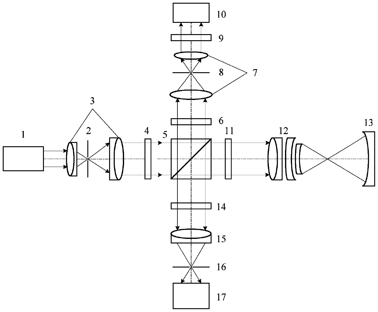
[0030] The spatial phase-shifting dynamic interferometer based on the liquid crystal spatial light modulator provided by the present invention, such as Figure 5 As shown, it includes: He-Ne laser 1, first pinhole filter 2, first collimator beam expander system 3, λ / 2 wave plate 4, polarization beam splitter prism 5, first λ / 4 wave plate 6, second Collimated beam expander system 7, second pinhole filter 8, polarizer 9, liquid crystal spatial light modulator 10, second λ / 4 wave plate 11, standard spherical lens 12, mirror under test 13, analyzer 14, imaging System 15, third pinhole filter 16 and photodetector 17; wherein:

[0031] The Gaussian film beam emitted by the He-Ne laser 1 passes through the microscope objective lens of the first collimator beam expander system 3, the first pinhole filter 2 and the telescopic objective lens of the first collimator beam expander system 3, and becomes uniform linearly polarized light, the azimuth angle of the linearly polarized light ch...


PUM


Abstract

The invention belongs to the technical field of optics, and particularly relates to a spatial phase shift dynamic interferometer based on a liquid crystal spatial light modulator and application of the spatial phase shift dynamic interferometer. The spatial phase shift dynamic interferometer based on the liquid crystal spatial light modulator comprises a He-Ne laser, a first pinhole filtering, a first collimation and beam expanding system, a lambda / 2 wave plate, a polarizing beamsplitting prism, a first lambda / 4 wave plate, a second collimation and beam expanding system, a second pinhole filtering, a polarizing film, the liquid crystal spatial light modulator, a second lambda / 4 wave plate, a standard spherical mirror, a measured mirror, a polarization analyzer, an imaging system, a third pinhole filtering and an optical detector, dynamic testing of an aspheric surface member and a free-form surface member is realized through coded modulation of SLM, the SLM is used for replacing a tinypolarization phase shift array to realize spatial phase modulation, the adjustment is simple, the tiny polarization phase shift array is not required, and the difficulty is greatly reduced. Accordingto the spatial phase shift dynamic interferometer based on the liquid crystal spatial light modulator and application of the spatial phase shift dynamic interferometer, the function of real-time dynamic display is achieved, low energy consumption, easy control and high speed are achieved, the spatial resolution ratio is easier to improve, and high-precision measurement is realized.

Description

technical field [0001] The invention belongs to the technical field of optical measurement, in particular to a spatial phase-shifting dynamic interferometer based on a liquid crystal spatial light modulator. Background technique [0002] The dynamic interferometer can obtain four interferograms with a phase difference of 90° at one time at a time to achieve high-precision measurement. At the same time, the dynamic interferometer has strong anti-vibration ability, which can eliminate the influence of airflow and environmental vibration on measurement in this way , can be applied to field testing and inspection of optical systems, or optical inspections in various complex environments. [0003] Phase shifting is an important link in the dynamic interferometer system. Phase shifting is to obtain fringe patterns generated by different phases, and obtain the surface pattern of the measured surface through the data relationship between multiple fringe patterns. Time phase-shift i...

Claims


Application Information

Patent Timeline
Patent Type & Authority Applications(China)
IPC IPC(8): G01B9/02G01B11/24
CPCG01B9/02055G01B11/2441
Inventor 贺文俊陈柯含熊振璁储雨豪贾文涛付跃刚
Owner CHANGCHUN UNIV OF SCI & TECH
Why Eureka
Try Eureka