Real-time detection method for spot welding nugget diameter

A technology for real-time detection of nugget diameter, applied in the direction of electric/magnetic diameter measurement, electric measurement, measurement device, etc., can solve the problem of inability to real-time detection of nugget diameter in spot welding of stainless steel and superalloy

Inactive Publication Date: 2005-04-27
NORTHWESTERN POLYTECHNICAL UNIV
View PDF0 Cites 27 Cited by
  • Summary
  • Abstract
  • Description
  • Claims
  • Application Information

AI Technical Summary

Benefits of technology

This technology allows for accurate detection of small particles on metal surfaces during laser beam melting (LBF). By measuring their size accurately, this helps improve the accuracy with which they are used in manufacture processes such as LFW process.

Problems solved by technology

In order to improve the accuracy and efficiency of spot winding processes, researchers have developed various techniques based upon different physical properties associated with resistivity changes over time. These include static resistance curves and molten pool sizes obtained from experiments conducted under specific conditions. Additionally, they found that certain metals like stainable steels may exhibit similar behavior patterns even if their chemical composition remains constant throughout the experimentation period.

Method used


Image

  • Real-time detection method for spot welding nugget diameter
  • Real-time detection method for spot welding nugget diameter
  • Real-time detection method for spot welding nugget diameter

Examples


Embodiment 1

[0018] Embodiment 1: to the 1Cr18Ni9Ti stainless steel specimen of 1+1 press Figure 5 The numbers shown are spot welded.

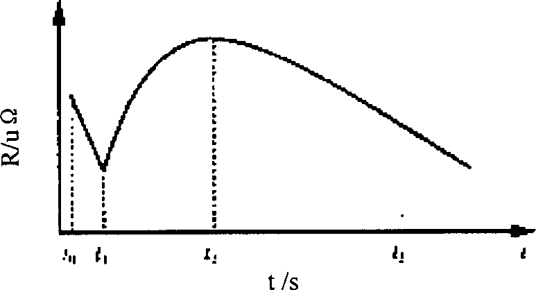
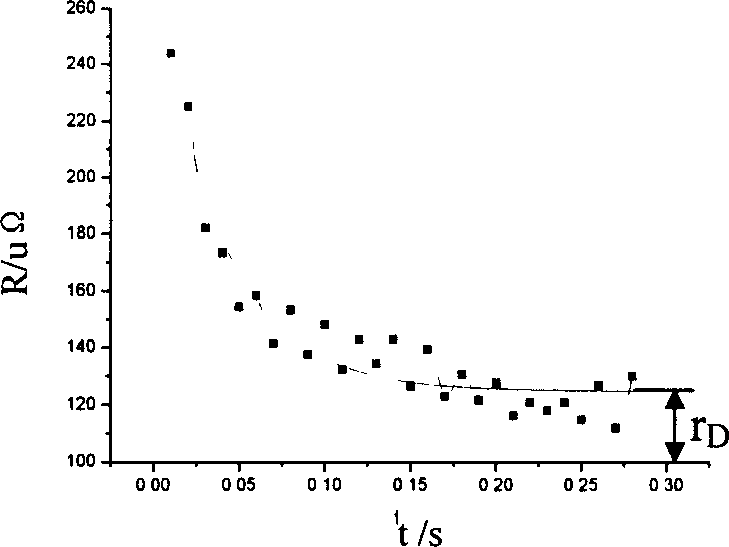
[0019] During spot welding, the welding current of each welding spot and the voltage signal between the upper and lower electrodes are input into the computer system for sampling, and the welding spot can be obtained by dividing the voltage peak value of each half cycle between the upper and lower electrodes by the corresponding welding current peak value The dynamic resistance value of each half cycle, the relationship between the dynamic resistance value and the power-on time is the dynamic resistance curve of the solder joint. The resistance value on the 1Cr18Ni9Ti stainless steel spot welding dynamic resistance curve when the slope is 6±1μΩ / s is called the quasi-steady-state resistance value r D , the quasi-steady-state resistance value r on the dynamic resistance curve D record it.

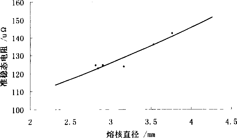
[0020] Use the above method to obtain the quasi-steady-state res...

Embodiment 2

[0031] Embodiment 2: to the GH4169 superalloy specimen of 1.5+1.5 press Figure 6 The numbers shown are spot welded.

[0032] During spot welding, the welding current of each welding spot and the voltage signal between the upper and lower electrodes are input into the computer system for sampling, and the welding spot can be obtained by dividing the voltage peak value of each half cycle between the upper and lower electrodes by the corresponding welding current peak value The dynamic resistance value of each half cycle, the relationship between the dynamic resistance value and the power-on time is the dynamic resistance curve of the solder joint. The resistance value on the GH4169 superalloy spot welding dynamic resistance curve when the slope is 6±1μΩ / s is called the quasi-steady state resistance value r D , the quasi-steady-state resistance value r on the dynamic resistance curve D record it.

[0033] Use the above method to obtain the quasi-steady-state resistance value ...


PUM


Abstract

The real-time dot welding molten kernel detecting method includes the following steps: performing several point welding with welded sample in the same thickness as the welded part, and measurement and calculation to obtain the dynamic resistance curve of each point; further obtaining the quasi-stable state resistances rD of each point; splitting the welded sample along the joint surface, measuring the molten kernel diameter dK of each welded point, and drawing the rD vs dK curve; storing rD vs dK curves of different material thickness in computer system; and comparing the practical molten kernel diameter with the set standard value to judge welding quality.

Description


Claims


Application Information

Patent Timeline
Owner NORTHWESTERN POLYTECHNICAL UNIV
Why Eureka
Try Eureka