Calibrated real time clock for acquisition of GPS signals during low power operation

A global positioning system, low-power technology, applied in the field of global positioning system receivers, can solve problems such as power consumption

Inactive Publication Date: 2005-04-27
SIRF TECHONOLOGY INC
View PDF1 Cites 16 Cited by
  • Summary
  • Abstract
  • Description
  • Claims
  • Application Information

AI Technical Summary

Problems solved by technology

However, since the GPS oscillator and associated timing system consume a lot of power, it is highly desirable to power down these components within a portable GPS receiver unit to conserve power resources

Method used


Image

  • Calibrated real time clock for acquisition of GPS signals during low power operation
  • Calibrated real time clock for acquisition of GPS signals during low power operation
  • Calibrated real time clock for acquisition of GPS signals during low power operation

Examples


Embodiment Construction

[0027] 1. Introduction to GPS environment.

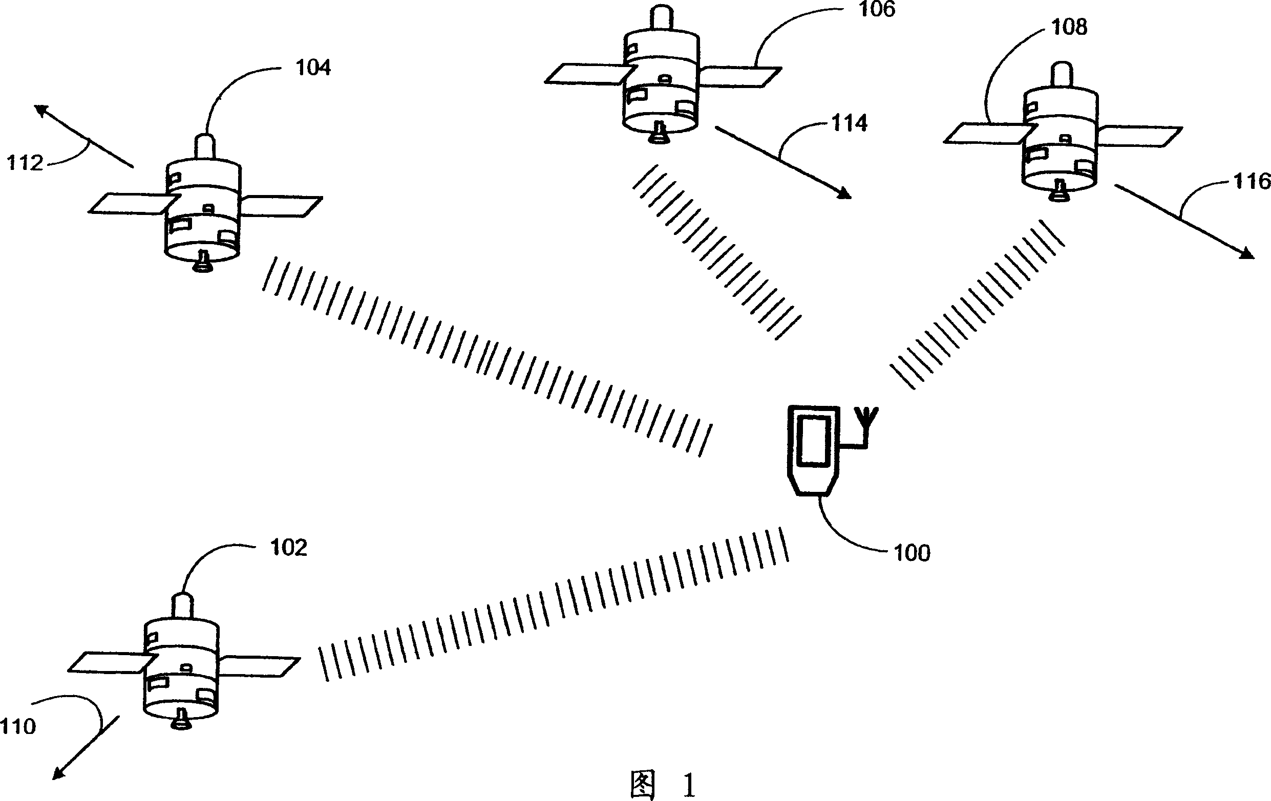
[0028] Figure 1 illustrates an example environment for the operation of a Global Positioning System (GPS) receiver. FIG. 1 shows a GPS receiver unit 100 and four GPS satellites 102 , 104 , 106 and 108 . Each satellite 102 , 104 , 106 and 108 transmits to the GPS receiver unit 100 . Satellite 102 travels at speed v a + Moving towards the GPS receiver unit 100 along the line of sight (LOS, line of sight) 110; the satellite 104 is moving at a velocity v b - is moving away from the GPS receiver unit 100 along the LOS 112; and the satellite 106 is moving at a velocity v c - Move away from the GPS receiver unit 100 along the LOS 106 . As a result, assuming a carrier wavelength of λ, the transmitted signal from satellite 102 experiences a positive Doppler shift The transmitted signal from satellite 104 experiences a negative Doppler shift while the transmitted signal from satellite 106 experiences a negative Doppler shift

[...


PUM


Abstract

Power is conserved in a Global Positioning System (GPS) receiver (100) by shutting down selected components during periods when the GPS receiver (100) is not actively calculating the GPS receiver location. A low power time keeping circuit (200) accurately preserves GPS time when the selected components are deactivated. When the selected components are turned on in response to a wake-up command, time provided from the low power time keeping circuit (200), corrected for actual operating temperatures, and data from the GPS clock temperature/frequency table (224), are used to recalibrate time from a GPS oscillator (204). Positions of the GPS satellites are then estimated such that the real GPS time is quickly determined from the received satellite signals. Once real GPS time is determined from the detected satellite signals, the selected components are deactivated. The process described above is repeated such that accurate GPS time is maintained by the low power time keeping circuit (200).

Description

technical field [0001] The present invention relates generally to Global Positioning System (GPS) receivers. Specifically, it relates to maintaining an accurate GPS receiver clock circuit during low power operation. Background technique [0002] The Global Positioning System (GPS) is a collection of 24 Earth-orbiting satellites. Each GPS satellite follows a precise orbit approximately 11,000 miles above the Earth's surface. A GPS receiver automatically tracks at least three satellites to determine its precise location. Each satellite transmits a signal modulated with a unique pseudonoise (PN) code. Each PN code is a sequence that repeats 1023 chips per millisecond consistent with a chip rate of 1.023 megahertz (MHz). Each satellite transmits on the same frequency. For civilian use, this frequency is called L1 and is 1575.42MHz. The GPS receiver receives the signal as a mixture of the transmitted signals of the satellites visible to the receiver. The receiver detects t...

Claims


Application Information

Patent Timeline
Patent Type & Authority Applications(China)
IPC IPC(8): G01S1/00G01S19/23G01S19/34G04C10/04G04F5/00G04G19/12G06F1/14G06F1/32
CPCG04C10/04G01S19/34G01S19/235G06F1/3203G01S19/23G04F5/00G06F1/14Y02B60/1217G04G19/12Y02D10/00G01S19/13
Inventor 史蒂文·A·格朗迈耶
Owner SIRF TECHONOLOGY INC
Why Eureka
Try Eureka