Triggering events in a welder with a real-time clock

a real-time clock and welder technology, applied in the field of construction tools, can solve the problems of dangerous places and saving power costs, and achieve the effect of saving power costs and saving time associated

Active Publication Date: 2006-08-03
LINCOLN GLOBAL INC
View PDF8 Cites 93 Cited by
  • Summary
  • Abstract
  • Description
  • Claims
  • Application Information

AI Technical Summary

Benefits of technology

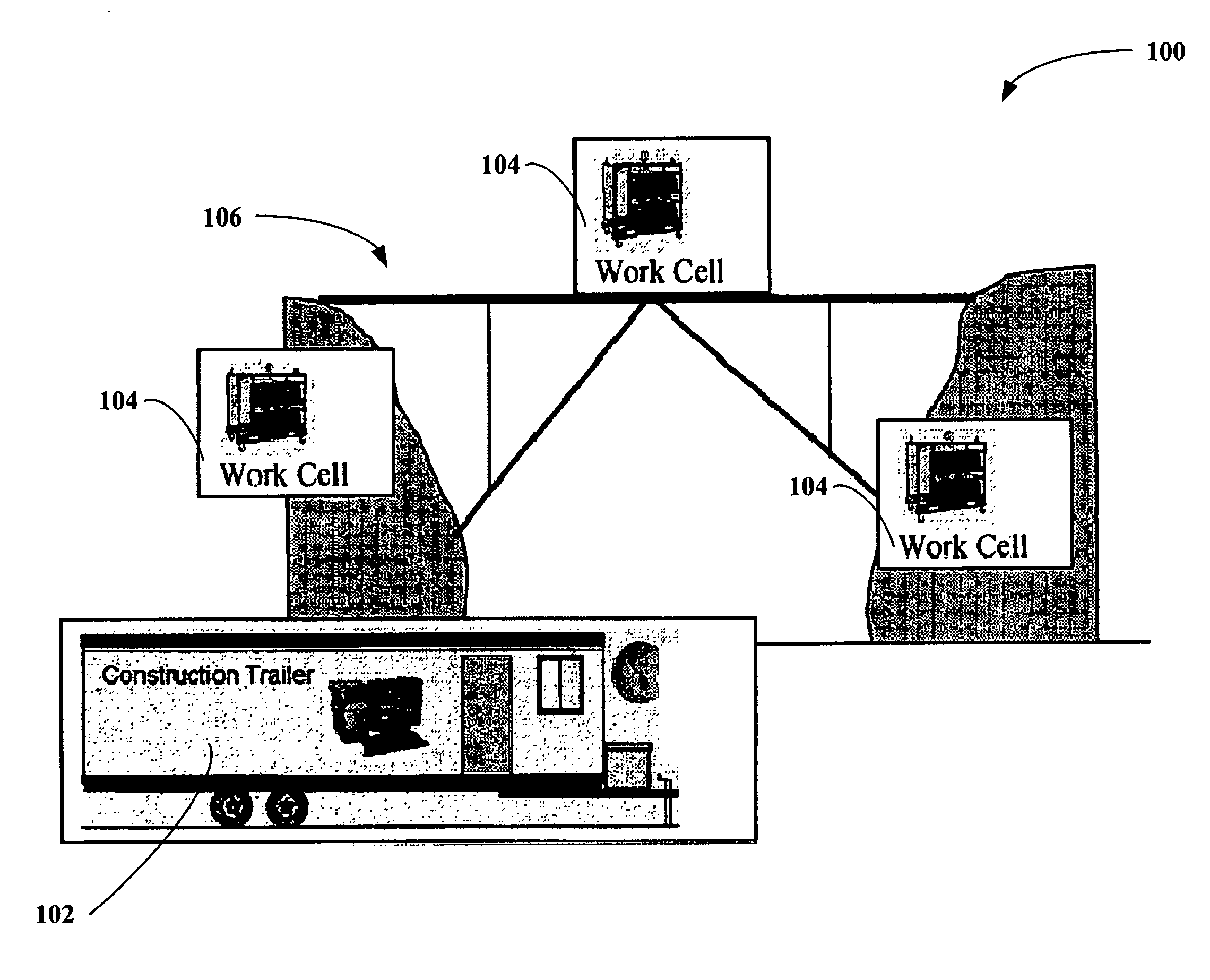
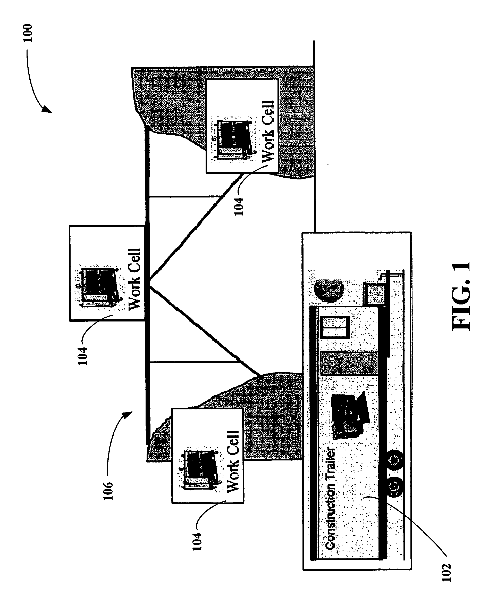
[0006] The subject invention relates to novel systems and / or methodologies for inducing an action at one or more remotely located welding devices based on triggering events. According to an aspect of the invention, triggering events can be employed to cause a control component to initiate an action at the welder and / or to ensure that a welder is operating in a proper mode and / or not operating. For example, triggering events can comprise temporal occurrences, such as a specific time (e.g., 05:00, 19:00, . . . ) and / or ranges of time (e.g., 14:00-15:00 . . . ). According to this example, an event such as 21:00, or 9 pm (e.g., based on a clock or timer, which can be associated with a welder) can trigger a local control component to initiate an action, such as a power-down protocol in the welder to ensure that the welder is not operational after 9 pm. In this manner, in the event that an operator failed to properly shut down / power off a remote welder, the welder can be automatically powered down after 9 pm, thus saving power costs. Additionally, welders are often located disparately throughout a manufacturing environment and can be position in dangerous places (e.g., an unfinished high rise building, bridge . . . ). By providing an automatic shut down signal based on a triggering event (e.g., 21:00), the system mitigates a need for an operator to be required to return to a welder to shut it down and saves time associated such a task as well.

Problems solved by technology

In this manner, in the event that an operator failed to properly shut down / power off a remote welder, the welder can be automatically powered down after 9 pm, thus saving power costs.
Additionally, welders are often located disparately throughout a manufacturing environment and can be position in dangerous places (e.g., an unfinished high rise building, bridge .

Method used


Image

  • Triggering events in a welder with a real-time clock
  • Triggering events in a welder with a real-time clock
  • Triggering events in a welder with a real-time clock

Examples


Embodiment Construction

[0020] The subject invention is now described with reference to the drawings, wherein like reference numerals are used to refer to like elements throughout. In the following description, for purposes of explanation, numerous specific details are set forth in order to provide a thorough understanding of the subject invention. It may be evident, however, that the subject invention may be practiced without these specific details. In other instances, well-known structures and devices are shown in block diagram form in order to facilitate describing the subject invention.

[0021] As used in this application, the terms “component,”“handler,”“model,”“system,” and the like are intended to refer to a computer-related entity, either hardware, a combination of hardware and software, software, or software in execution. For example, a component may be, but is not limited to being, a process running on a processor, a processor, an object, an executable, a thread of execution, a program, a computer...


PUM

PropertyMeasurementUnit
timeaaaaaaaaaa
operating timeaaaaaaaaaa
poweraaaaaaaaaa

Abstract

Systems and methods are disclosed that facilitate inducing one or more actions, such as generation of a shift report data related to construction device(s), via detection of specified triggering events. The system comprises a triggering component that determines whether a triggering event has occurred a control component that initiates an action in response to the triggering event. Triggering events can comprise specific times of day as determined by a real-time clock that can be associated with a construction / fabrication device, such as a welder. Additionally, actions responsive to triggering events can be tagged for human approval prior to initiation in order to provide system flexibility.

Description

TECHNICAL FIELD [0001] The subject invention relates generally to control of construction tools in a manufacturing environment, and more particularly to triggering action(s) in disparately located devices within the manufacturing environment. BACKGROUND OF THE INVENTION [0002] Welding systems reside at the core of the modern industrial age. From massive automobile assembly operations to automated manufacturing environments, these systems facilitate joining in ever more complicated manufacturing operations. One such example of a welding system includes an electric arc welding system. This may involve movement of a consumable electrode, for example, toward a work piece while current is passed through the electrode and across an arc developed between the electrode and the work piece. The electrode may be a non-consumable or consumable type, wherein portions of the electrode may be melted and deposited on the work piece. Often, hundreds or perhaps thousands of welders are employed to dr...

Claims


Application Information

Patent Timeline
Patent Type & Authority Applications(United States)
IPC IPC(8): B23K9/095
CPCB23K9/1087B23K31/00
Inventor KAINEC, STEPHEN M.HILLEN, EDWARD D.
Owner LINCOLN GLOBAL INC
Why Eureka
Try Eureka