

Underground gas collecting drilling tool
A drilling tool and earth gas technology, applied in the field of gas sampling devices, can solve the problems of affecting the gas concentration and the damage of the static environment of the soil layer, etc.
- Summary
- Abstract
- Description
- Claims
- Application Information
AI Technical Summary
Problems solved by technology
Method used
Image

Examples
Embodiment Construction
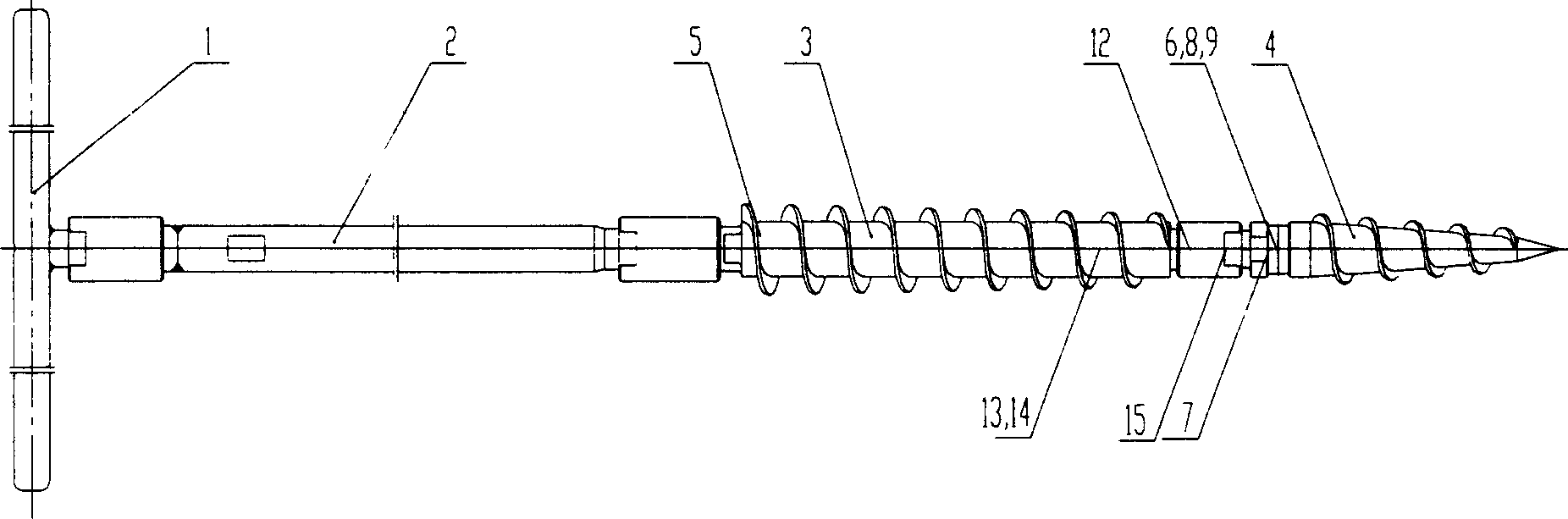
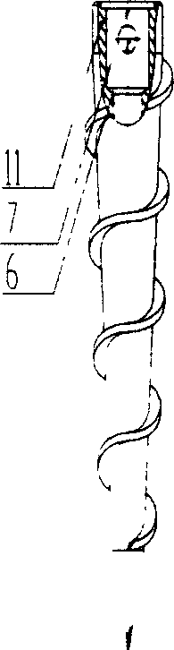
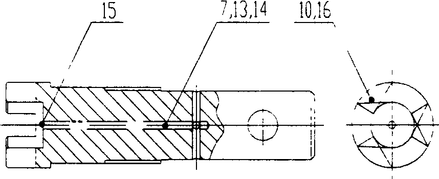
[0015] figure 1 It is an overall schematic diagram of the present invention: the handle 1 assists people to manually drill the drill bit 4 into the soil, and the handle 1 and the drill rod 2 adopt image 3 Connect the male and female bayonet fittings shown. This connection method can make the drilling tool adapt to the collection needs of different depths. The deeper the collection, the more drill pipes are needed. The bayonet butt screw fixed reverse anti-falling technology is adopted, so that the drilling tool can maintain the tightness of the connection in the state of forward rotation or reverse rotation. It ensures that the drill pipe can be added without lifting the drill during the drilling process, so as to meet the sampling requirements of different depths. The bayonet butt joint screw fixation anti-falling off technology is applied to the butt joint of each component of the present invention. There is a through hole in the center of the drill rod 2, and a capillar...
PUM
 Abstract
Description
Claims
Application Information