Back light module assembly

A backlight module and light guide plate technology, which is applied in optics, nonlinear optics, instruments, etc., can solve problems such as poor light uniformity, and achieve the effect of improving light uniformity

Inactive Publication Date: 2005-05-04
HONG FU JIN PRECISION IND (SHENZHEN) CO LTD +1
View PDF0 Cites 12 Cited by
  • Summary
  • Abstract
  • Description
  • Claims
  • Application Information

AI Technical Summary

Problems solved by technology

[0004] In order to overcome the problem of poor light uniformity of the backlight module in

Method used


Image

  • Back light module assembly
  • Back light module assembly
  • Back light module assembly

Examples


Embodiment Construction

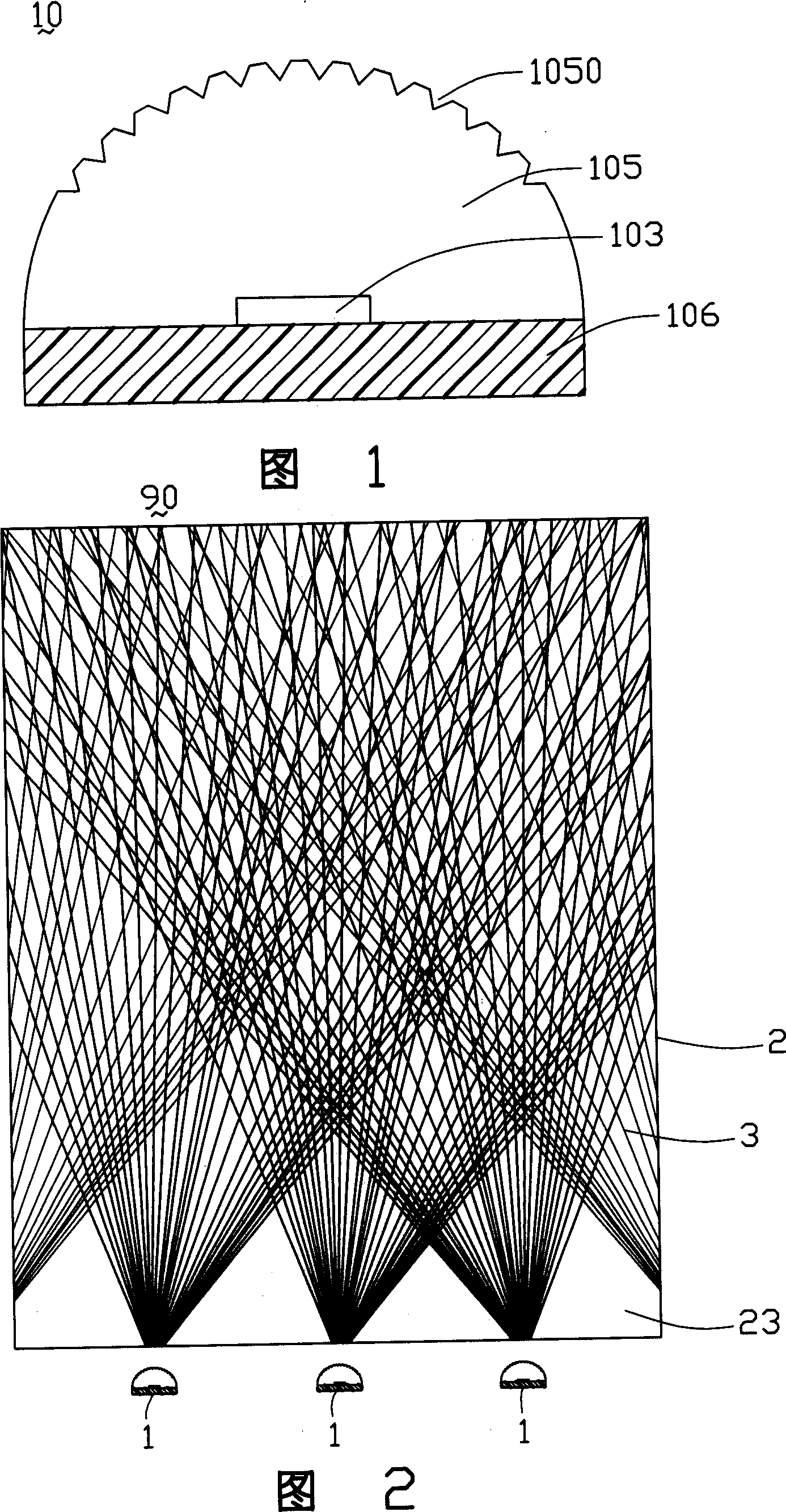
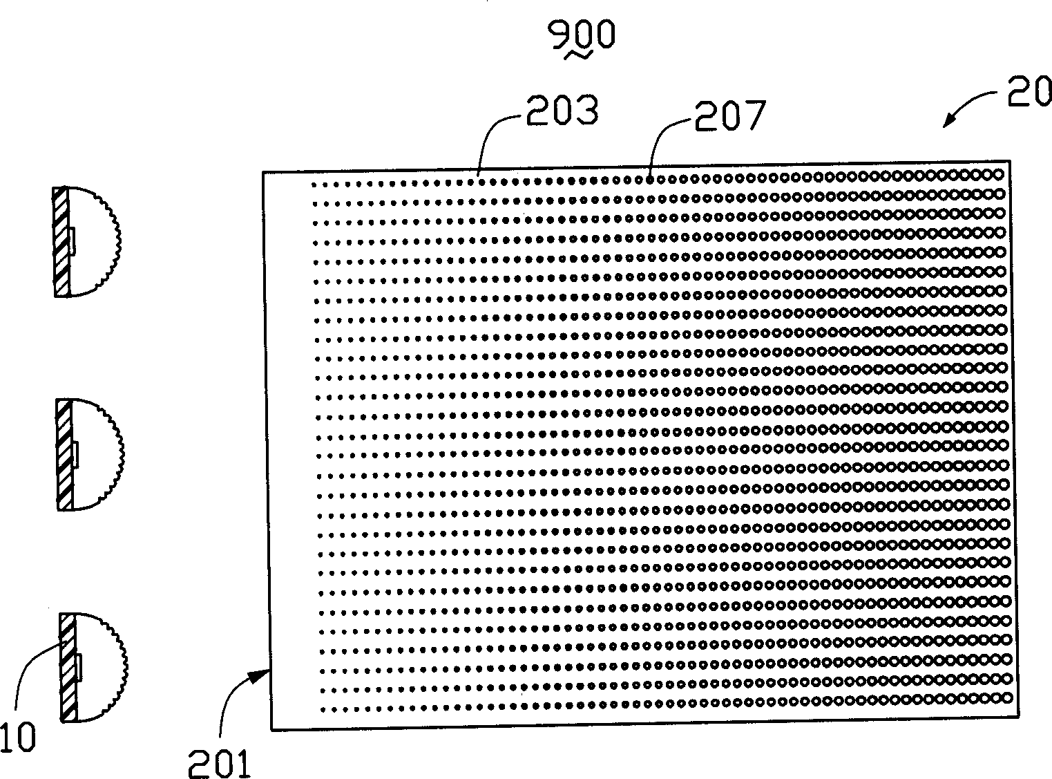
[0013] see image 3 , is a bottom view of the backlight module of the present invention, the backlight module 900 includes a plurality of light emitting diodes 10 and a light guide plate 20 . The plurality of light emitting diodes 10 are used to emit light beams, and the light guide plate 20 is used to guide the transmission direction of the light beams emitted by the plurality of light emitting diodes 10 to convert them into surface light sources for emission. The light guide plate 20 is flat and made of transparent materials such as acrylic, glass or polycarbonate. The bottom surface 203 of. The incident surface 201 is used to receive the light beam emitted by the LED 10 . The exit surface can be processed into a rough surface with a certain roughness. The bottom surface 203 of the light guide plate 20 is provided with a plurality of dots 207 , and the dots 207 are used to improve the luminance and uniformity of the light beam emitted from the light guide plate 20 . The s...


PUM

PropertyMeasurementUnit
Heightaaaaaaaaaa

Abstract

The invention is a backlight module, comprising a light guide plate and at least a LED, where the light guide plate includes at least a light incoming surface, a light outgoing surface connected with the former, the LED is arranged opposite the light incoming surface, the LED includes a substrate, a light emitting chip and a packaging structure, the packaging structure coats the light emitting chip and forms a light outgoing surface, the outgoing surface has many V-shaped grooves, the packaging structure is made of transparent piezoelectric material, and the transparent piezoelectric material has its mechanical deformation controlled by an external circuit.

Description

【Technical field】 [0001] The invention relates to a backlight module, in particular to a backlight module applied to a liquid crystal display. 【Background technique】 [0002] Because light-emitting diodes save power and have high brightness, they are widely used in backlight modules of mobile phones, PDAs (Personal Digital Assistants), and displays. The structure of the light emitting diode 1 can be referred to FIG. 1 , the light emitting diode 1 includes a substrate 16 and a light emitting chip 13 , the light emitting chip 13 is fixed on the substrate 16 and covered by the encapsulation structure 15 . The packaging structure 15 has a plurality of V-shaped grooves 151 on the surface, and the multiple V-shaped grooves 151 can diverge the emitted light of the light emitting diode 1. The packaging structure 15 uses transparent epoxy resin as the packaging material, and the epoxy resin has excellent adhesion. Good electrical insulation, heat resistance, chemical stability, shri...

Claims


Application Information

Patent Timeline
IPC IPC(8): G02F1/13357H01L33/00
Inventor 吕昌岳陈杰良余泰成
Owner HONG FU JIN PRECISION IND (SHENZHEN) CO LTD
Why Eureka
Try Eureka