Supercharge Your Innovation With Domain-Expert AI Agents!

Low air pressure switch for automobile

一种低气压、开关的技术,应用在电开关、电气元件、电路等方向,能够解决重大安全等问题

Inactive Publication Date: 2005-05-04
HYUNDAI MOTOR CO LTD
View PDF0 Cites 0 Cited by
  • Summary
  • Abstract
  • Description
  • Claims
  • Application Information

AI Technical Summary

Problems solved by technology

[0008] Because the primary function of the low air pressure switch is to check the air pressure of the air brake system, failure of the switch can cause major safety concerns

Method used


Image

  • Low air pressure switch for automobile
  • Low air pressure switch for automobile

Examples


Embodiment Construction

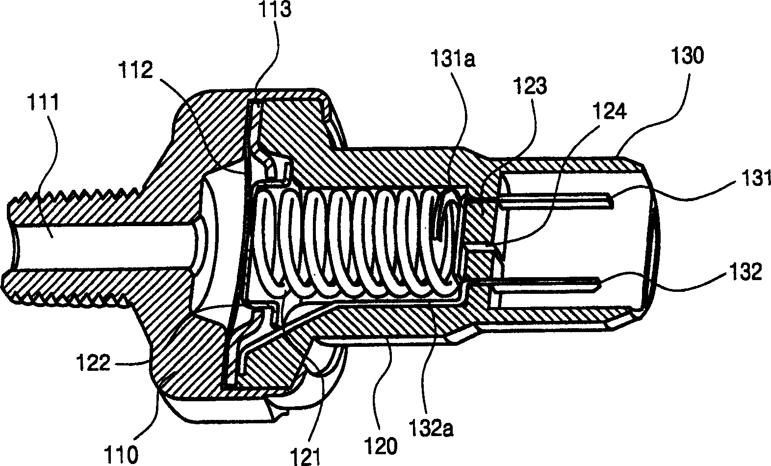
[0014] like figure 1 and figure 2 , the switch body 110 and the switch sleeve 120 are assembled into a low pressure switch body. The switch body includes a diaphragm 112 that operates correspondingly as the air pressure provided through the air inlet 111 changes, and a controller 122 elastically supported by a spring 121 . A contact plate 113 is placed between the diaphragm 112 and the controller 122 , and it selectively contacts the controller 122 according to the movement of the controller 122 .

[0015] Typically, the air inlet 111 is connected to the pneumatic lines of the vehicle, such as the pneumatic lines of the air brake system. The diaphragm 112 is switched on and off according to the air pressure state passing through the air inlet 111 , such as the pressure in the pneumatic line. The spring 121 serves as an element for determining a predetermined operating pressure of the switch. When the air pressure in the pneumatic line drops below a predetermined level, th...


PUM


Abstract

A low air pressure switch for an automobile is formed in a water resistance structure in which a connector has an integral terminal and switch body so that a moisture input passage into the interior of a switch is fully disconnected. An air outlet for an air discharge in a spring chamber of the switch body is formed inside the connector and air is discharged through the interior of the connector and a wire core. Therefore, it is possible to effectively prevent moisture from being introduced into the interior of the switch, so that a reliability and durability of the switch are enhanced.

Description

[0001] Cross References to Related Applications [0002] This application claims priority from Korean Application No. 2003-0076147 filed on October 30, 2003, which is incorporated herein by reference. technical field [0003] In general, the present invention relates to low air pressure switches for vehicles. More specifically, it effectively reduces the penetration of moisture into the interior of the low air pressure switch to improve the reliability and durability of the low air pressure switch. Background technique [0004] Generally speaking, low air pressure switches are suitable for pneumatic lines of large vehicles such as buses and trucks. A low air pressure switch is installed in a pneumatic line, such as that of an air brake system, to detect a drop in air pressure below a predetermined air pressure value. When the air pressure is below a certain level, the low air pressure switch is on. With the switch turned on, the warning light will illuminate and an alarm ...

Claims


Application Information

Patent Timeline
Patent Type & Authority Applications(China)
IPC IPC(8): H01H9/04H01H35/34
CPCH01H35/34H01H9/047
Inventor 李健钟
Owner HYUNDAI MOTOR CO LTD
Features
  • R&D
  • Intellectual Property
  • Life Sciences
  • Materials
  • Tech Scout
  • Unparalleled Data Quality
  • Higher Quality Content
  • 60% Fewer Hallucinations
Learn More