Hydro-mechanical continuously variable transmission

A transmission, variable technology, applied in transmissions, gear transmissions, fluid transmissions, etc., can solve problems such as low efficiency and insufficient to ensure the effective use of the available power of the engine

Inactive Publication Date: 2005-05-04
SILVATECH GLOBAL SYST
View PDF0 Cites 10 Cited by
  • Summary
  • Abstract
  • Description
  • Claims
  • Application Information

AI Technical Summary

Problems solved by technology

A purely mechanical drive is insufficient to ensure efficient use of the power available to the engine, caused by discontinuous speed ratios, while a purely hydraulic drive has inherent inefficiencies at higher operating speeds

Method used


Image

  • Hydro-mechanical continuously variable transmission
  • Hydro-mechanical continuously variable transmission
  • Hydro-mechanical continuously variable transmission

Examples


Embodiment Construction

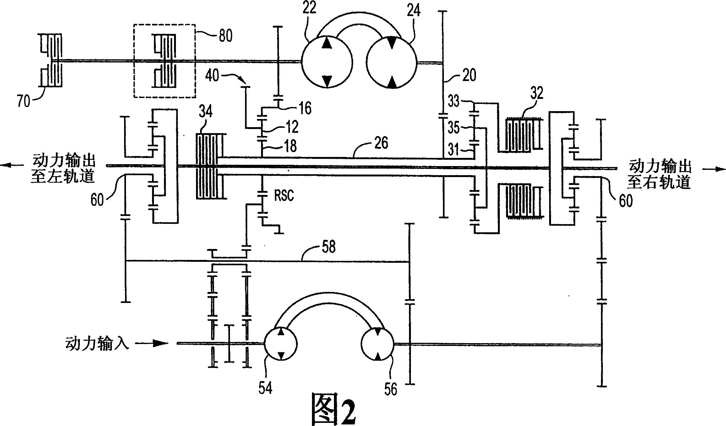
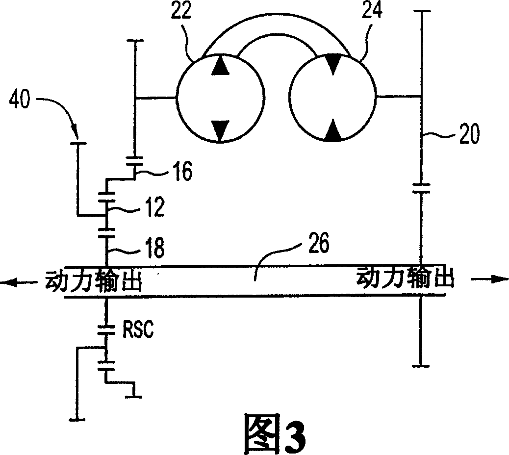
[0029] A hydromechanical continuously variable transmission (HMCVT) is used to split the input power between hydraulic drive branches and parallel mechanical drive branches and recombine the power from each branch into a single output, where the hydraulic drive branch uses hydraulic pumps and Motors, mechanical drive branches using shafts and / or gears.

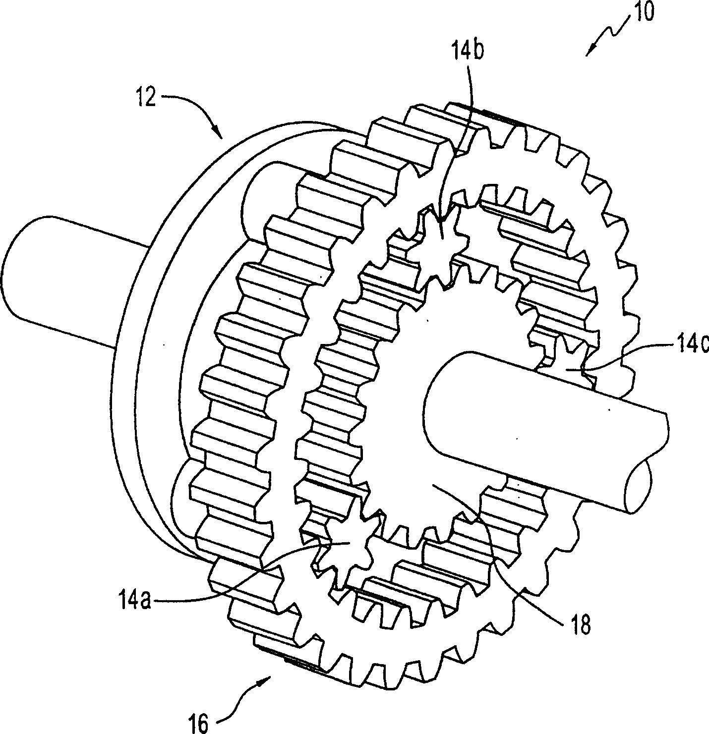
[0030] HMCVT with figure 1 The illustrated planetary gear set 10 is the basis. The planetary gear set 10 includes four parts: a carrier gear 12 ; planetary gears 14 ; a ring gear 16 and a sun gear 18 . The ring gear 16 and the sun gear 18 are connected by planetary gears 14 . The planet gears 14 are also connected to the carrier gear 12 . exist figure 1 In , three planetary gears 14a-c are used, more can be used if desired.

[0031] Planetary gear set 10 is connected to hydraulically driven pump 22 (see FIG. 2 ), main shaft 26 and transmission input 40 . For descriptive purposes, a three-letter code (R=ring gear; S=sun g...


PUM


Abstract

The invention comprises a hydro-mechanical continuously variable transmission (HMCVT) that uses a planetary gear system to provide a combination of hydraulic and mechanical power for a vehicle or stationary equipment. The invention further comprises various ancillary elements to improve the performance of the HMCVT.

Description

technical field [0001] The present invention relates to a drive system for use as a vehicle propulsion system or a stationary equipment drive in which mechanical and hydraulic power systems are combined. Background technique [0002] Hydraulic drive systems are typically used in large vehicles or stationary equipment. However, as the output speed increases for a given gear set, the efficiency of the hydraulic drive decreases accordingly. This makes it inefficient to run the hydraulic drive in the upper half of the gear set. This problem can be overcome by having multiple gear sets, but the complexity of the final transmission negates the advantage of using hydraulic drives. [0003] An alternative to a hydraulic drive system is a mechanical drive system. However, conventional mechanical drive systems are limited to discrete transmission ratios, which do not allow for infinitely variable speed ratios such as occur in hydraulic drives. For transmission efficiency, a great ...

Claims


Application Information

Patent Timeline
Patent Type & Authority Applications(China)
IPC IPC(8): F16H3/72B62D11/18F16H47/04
CPCB62D11/18F16H2047/045F16H47/04F16H2037/088
Inventor 杰拉尔德·戴克保罗·德赖斯
Owner SILVATECH GLOBAL SYST
Why Eureka
Try Eureka