
A connector housing assembly and an electric connector assembly

A technology of electrical connectors and connectors, which is applied to parts, connections, electrical components, etc. of connecting devices, can solve problems such as rising production costs, difficult operation, and reduced productivity, and achieve the effect of realizing productivity

Inactive Publication Date: 2005-05-11
JST MFG CO LTD
View PDF3 Cites 5 Cited by
  • Summary
  • Abstract
  • Description
  • Claims
  • Application Information

AI Technical Summary

Problems solved by technology

[0003] For example, the electric connector that is arranged in the interior of small-sized electronic equipment such as mobile phone expects compactness, as this small-sized electric connector, under the situation that adopts the electric connector that has above-mentioned connector case main body and cover, The operation of pinching the cover to fit the connector housing body is difficult, and the operator needs proficiency and time. Even if the cover is fitted to the connector housing body mechanically, an additional design is required to securely grasp it. A special mechanism for holding a smaller cap will lead to a decrease in productivity and an increase in production cost in any case
In addition, regardless of the size of the electrical connector, when fitting the cover on the connector housing body in a narrow space, the operation of fitting the cover on the connector housing body is very difficult, and the operator needs proficiency and time. Even if the fitting of the cover on the connector housing body is performed mechanically, more complicated mechanical movements are required than usual, which leads to a decrease in productivity and an increase in production cost in any case.

Method used


Image

  • A connector housing assembly and an electric connector assembly
  • A connector housing assembly and an electric connector assembly
  • A connector housing assembly and an electric connector assembly

Examples


Embodiment Construction

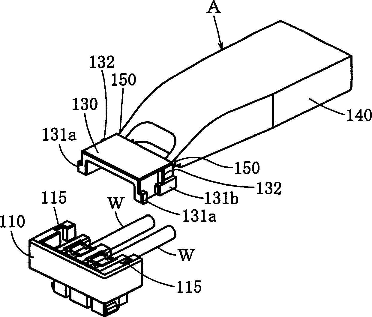
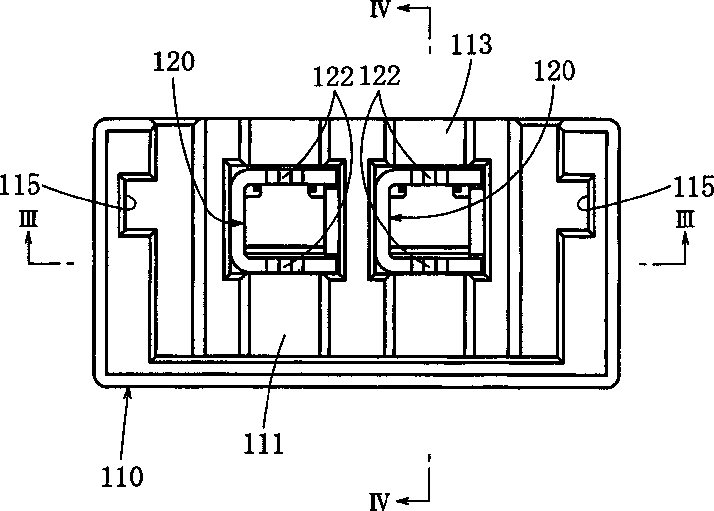
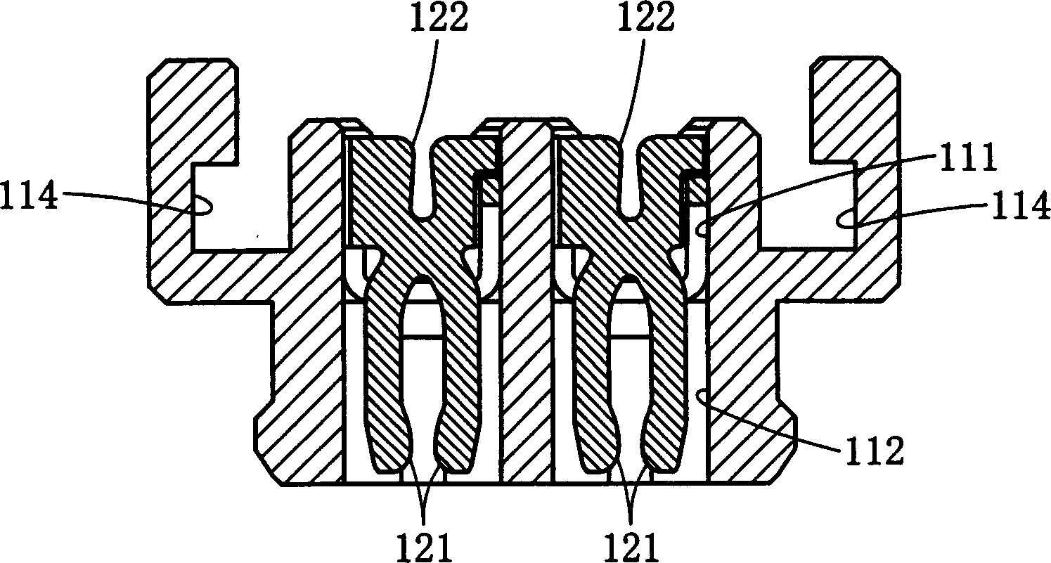
[0039] Hereinafter, examples of the present invention will be described. figure 1 A connector housing assembly according to a first embodiment of the present invention is shown. The connector housing assembly is assembled in Figure 13 ~ Figure 15 The electrical connector 100 shown is used. The electrical connector 100 is a receptacle connector, such as Figure 16 As shown, the electrical connector 100 is fitted to a header connector 200 mounted on a printed circuit board or the like, but the form and usage of the electrical connector of the present invention are not limited thereto. The electrical connector 100 has: a connector housing body 110 formed of an insulating material; contacts 120 formed on the connector housing body 110 formed of a conductive material; The cover 130 on the main body 110 of the device housing. It is assumed that a depth direction, a width direction, and a height direction perpendicular to each other are set, and these directions are added for de...


PUM


Abstract

A connector housing assembly and an electrical connector assembly. The purpose of the present invention is to simplify the operation of fitting the cover on the main body of the connector housing, improve the productivity of the electronic connector, and reduce the production cost. It includes: a connector housing main body (110) provided with an accommodation chamber (111) open to the outside; contacts (120) accommodated in the connector housing main body (110) so as to be able to contact contacts on the opposite side and fit on the cover (130) of the housing chamber (111) on the connector housing main body (110), which is configured to connect the electric wire (W) of the contact (120) from the connector housing main body (110) and Between the covers (130) is drawn out to the outside. A connector housing main body (110) and a cover assembly part (A) formed by connecting an auxiliary part (140) to a cover (130) via a cutable connection part (150) are combined.

Description

technical field [0001] The invention belongs to the field of electrical connectors, and in particular relates to a connector shell assembly and an electrical connector assembly used to assemble an electrical connector connected with electric wires. Background technique [0002] JP-A-2002-164092, JP-A-2001-43926 and JP-11-185868 disclose an electrical connector, which has: a connector housing main body with a storage chamber open to the outside; The contact that is accommodated in the main body of the connector housing so that it can contact the contact on the other side; the cover that fits on the main body of the connector housing to cover the storage chamber, and the wires that connect the contacts are drawn from between the main body of the connector housing and the cover. lead to the outside. [0003] For example, the electric connector that is arranged in the interior of small-sized electronic equipment such as mobile phone expects compactness, as this small-sized elec...

Claims


Application Information

Patent Timeline
IPC IPC(8): H01R13/56H01R4/24H01R13/11H01R13/115H01R13/46H01R13/506
CPCH01R4/2454H01R13/112H01R13/506H01R13/46
Inventor 黑田桂治森分良堀内秀晃
Owner JST MFG CO LTD
Learn More