Light conducting board and back light module

A backlight module and light guide plate technology, applied in optics, nonlinear optics, instruments, etc., can solve the problems of high cost of light guide plate, high cost of backlight module, low light utilization rate, etc., achieve low cost, omit glue Process, the effect of high light utilization

Inactive Publication Date: 2005-05-25
HONG FU JIN PRECISION IND (SHENZHEN) CO LTD +1
View PDF1 Cites 28 Cited by
  • Summary
  • Abstract
  • Description
  • Claims
  • Application Information

AI Technical Summary

Problems solved by technology

[0004] In order to overcome the disadvantages of high cost and low light utilization rate of the prior art light guide plate, the present invention provides a light guide plate with low cost and high light utilization ra

Method used


Image

  • Light conducting board and back light module
  • Light conducting board and back light module
  • Light conducting board and back light module

Examples


Embodiment Construction

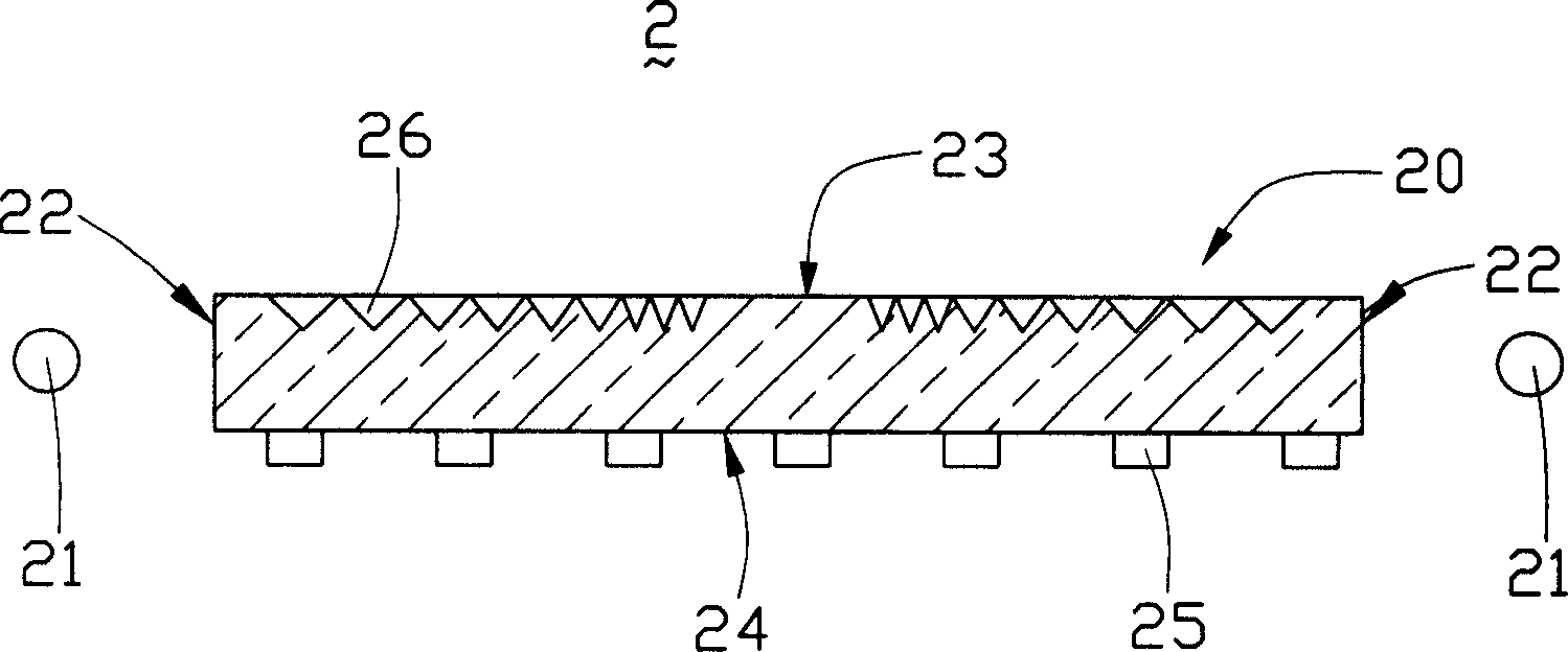
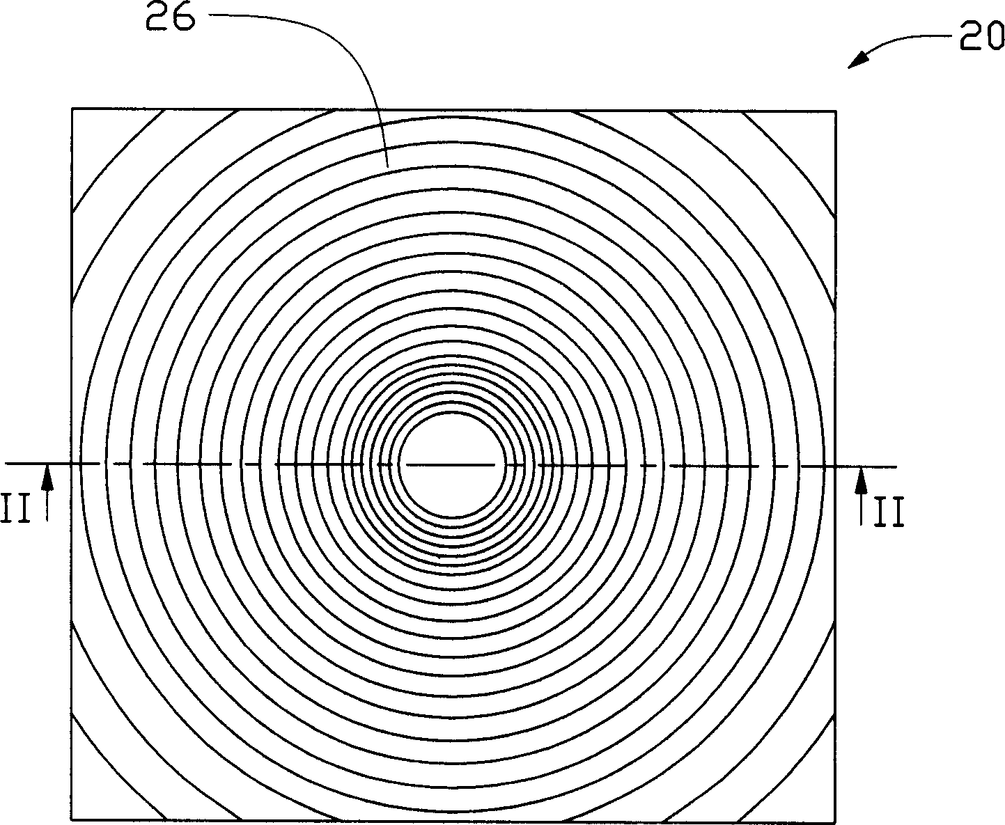
[0013] Please also refer to figure 2 and image 3 , are respectively the side view and the top view of the light guide plate of the first embodiment of the backlight module of the present invention. The backlight module 2 includes a light guide plate 20 and two light sources 21 . The light guide plate 20 is flat, and its material can be acrylic resin, polycarbonate, polyethylene resin or glass. The light guide plate 20 includes two opposite light incident surfaces 22 , a light exit surface 23 adjacent to the two light incident surfaces 22 , and a bottom surface 24 opposite to the light exit surfaces 23 . Wherein, the light-emitting surface 23 is provided with concentric circular grooves 26 with varying pitches. The concentric circular grooves 26 are concentric circular structures formed by gradually spreading outward from the center of the light guide plate 20, wherein the cross-section of each groove is V It can also be trapezoidal, arc-shaped, elliptical, etc. The conce...


PUM


Abstract

The present invention relates to a light-conducting plate, including a light-incoming plane, a light-outcoming plane adjacent to said light-incoming plane and a background plane opposite to said light-outcoming plane. On said light-outcoming plane the concentric channels whose spacing distances are changed are set.

Description

【Technical field】 [0001] The invention relates to a light guide plate and a backlight module using the light guide plate. 【Background technique】 [0002] Liquid crystal display devices are mainly used in various information, communication, and consumer products, such as personal computers, LCD TVs, mobile phones, video phones, and PDAs. Because the liquid crystal display panel itself cannot emit light, it needs a backlight module to provide it with uniform plane light, so as to obtain a good visual effect. [0003] see figure 1 , is a prior art backlight module disclosed in US Patent No. 5,548,670 published on August 20, 1996. The backlight module 1 includes light sources 101 and 102 arranged parallel to each other, a light guide plate 12 arranged between the light sources 101 and 102, a reflector 13 arranged below the light guide plate 12, and a prism located above the light guide plate 12. slice 14. In the backlight module 1 , since the light guide plate 12 does not ha...

Claims


Application Information

Patent Timeline
IPC IPC(8): G02F1/1335
Inventor 郑文峰
Owner HONG FU JIN PRECISION IND (SHENZHEN) CO LTD
Why Eureka
Try Eureka