RF circuit for minidisc regeneration apparatus

A technology of RF circuit and regenerative device, applied in the field of RF circuit, can solve problems such as faults caused by tracking correction

Inactive Publication Date: 2005-06-08
SANYO ELECTRIC CO LTD
View PDF1 Cites 0 Cited by
  • Summary
  • Abstract
  • Description
  • Claims
  • Application Information

AI Technical Summary

Problems solved by technology

Therefore, at the end of the period in which the level of the RF signal decreases, the level of the TE signal fluctuates in conjunction with the level fluctuation of the RF signal ( Figure 4 Arrow B), as a result, depending on the situation, there is a problem that there is a problem in tracking correction, etc.
In addition, although not shown in the figure, the same level variation occurs in the FE signal

Method used


Image

  • RF circuit for minidisc regeneration apparatus
  • RF circuit for minidisc regeneration apparatus
  • RF circuit for minidisc regeneration apparatus

Examples


Embodiment Construction

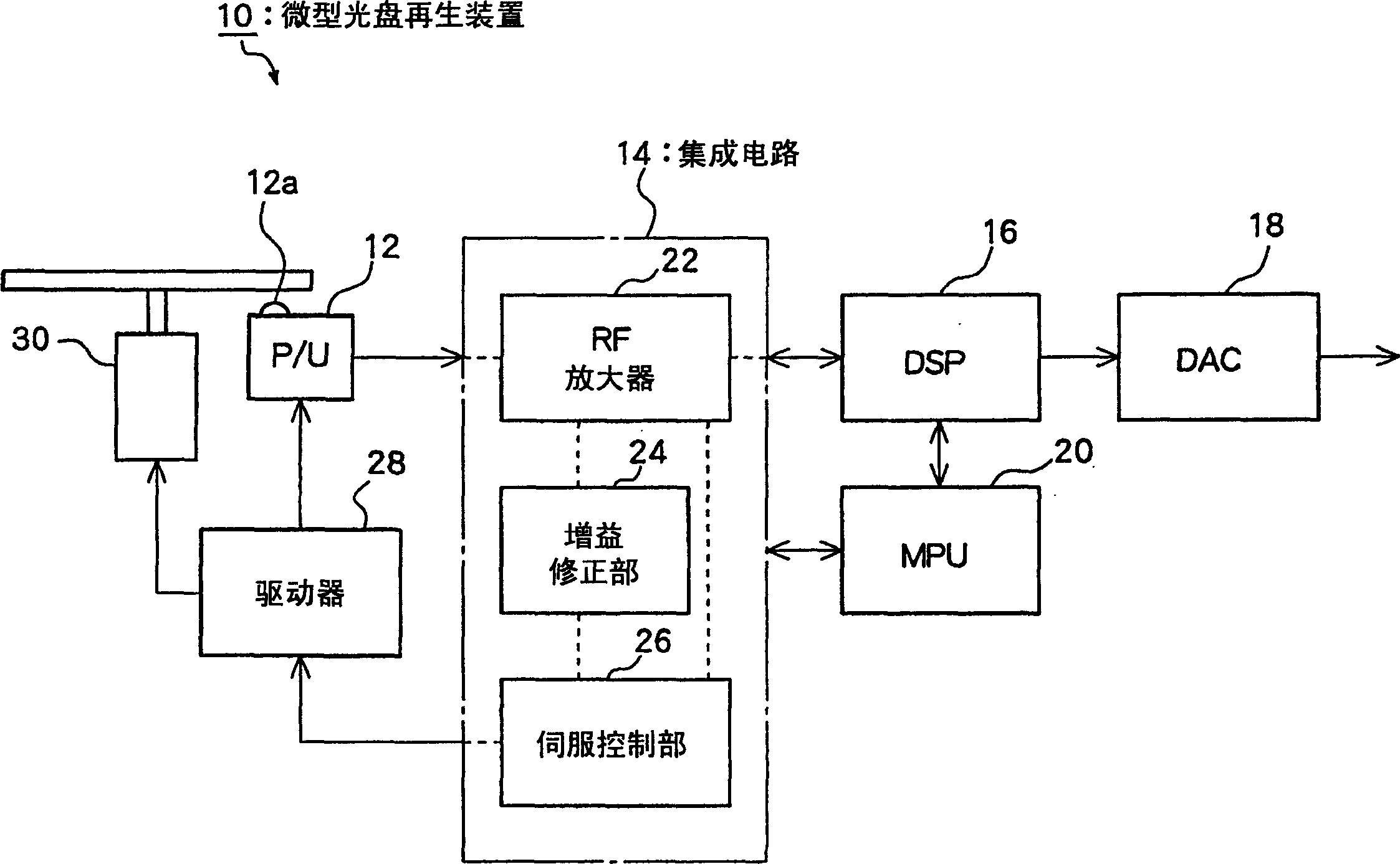
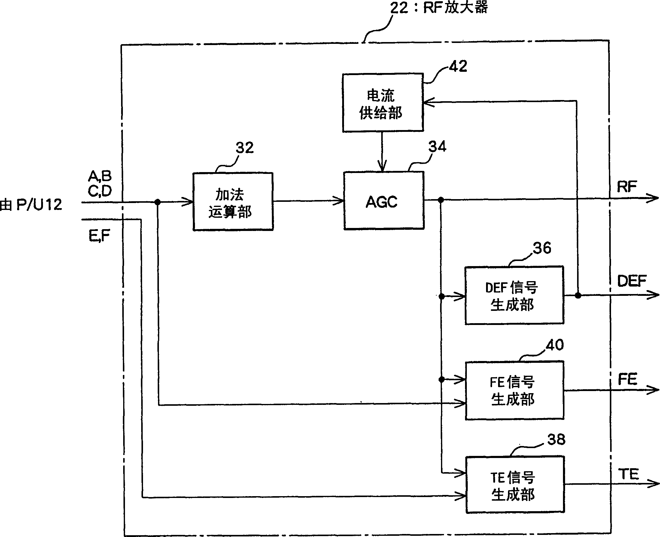
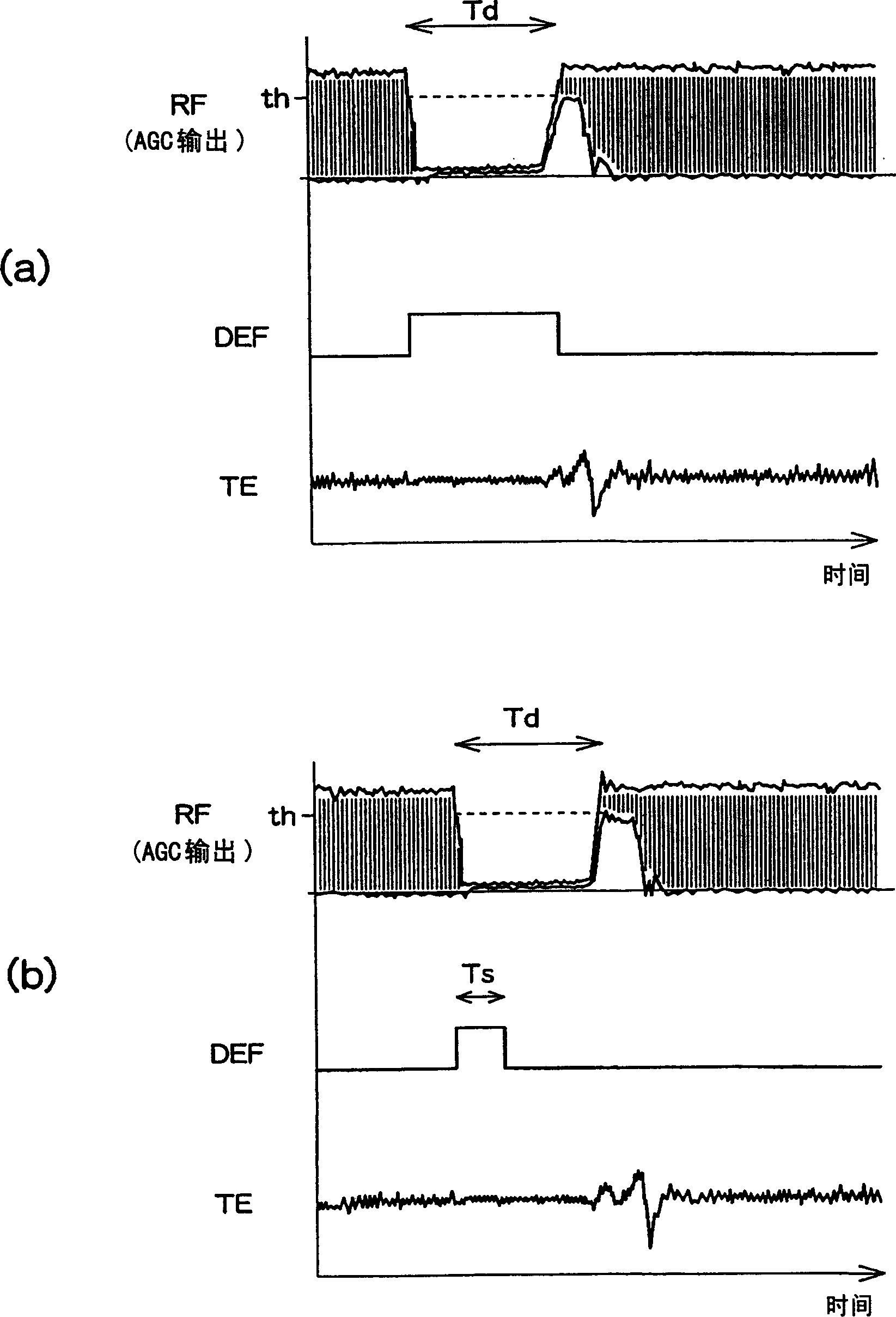
[0020] Hereinafter, preferred embodiments of the present invention will be described with reference to the drawings. figure 1 is a diagram showing an example of the configuration of important parts of the miniature disc playback device 10 according to this embodiment, figure 2 It is a diagram showing an example of the configuration of important parts of the RF amplifier (RF circuit) included in the miniature disc playback device 10, and image 3 It is a diagram showing an example of the waveform of each signal (RF, DEF, TE signal) generated in the RF amplifier 22 . In addition, in image 3 In the middle, the upper section is RF, the middle section is DEF, and the lower section is TE. The horizontal axis is time, and the vertical axis is the level of each signal.

[0021] figure 1 The disc reproducing apparatus 10 includes a pickup 12 , an integrated circuit 14 , a DSP (Digital Signal Processor) 16 , a DAC (Digital to Analog Converter) 18 , an MPU (Micro Processing Unit) ...


PUM


Abstract

The present invention provides an RF circuit for a miniature disk reproducing device that suppresses fluctuations in RF signals caused by scratches on an optical disk or the like. When the automatic gain control amplifying unit (AGC) (34) detects that the RF signal is equal to or lower than the prescribed level by the DEF signal generating unit (36) (RF signal level detecting unit), it is different from when it is not detected. ratio, suppressing the magnification low. This suppresses the level increase and fluctuation of the RF signal when recovering from a state of level drop caused by scratches or the like.

Description

technical field [0001] The present invention relates to an RF circuit for performing RF (Rdio Frequency) signal processing in a micro-disc reproducing device. Background technique [0002] Conventionally, in miniature disc reproduction devices, clock regeneration, synchronous detection, demodulation, error detection, error correction, etc. The digital signal processing unit (DSP) for processing, the D / A converter (DAC) for analog conversion of the output signal of the DSP, etc., to generate the final output signal. [0003] Among them, the RF amplifier is provided with an automatic gain control amplifying unit (AGC) that should substantially equalize the amplitude level of the RF signal. And, the RF signal output from the AGC is input to the DSP. [0004] Furthermore, the RF amplifier is provided with: a tracking error output signal generating unit (TE signal generating unit) for generating a tracking error output signal (TE signal); and a focus error output signal generat...

Claims


Application Information

Patent Timeline
Patent Type & Authority Applications(China)
IPC IPC(8): G11B20/10G11B7/005G11B7/09G11B20/00H03G3/30H04B1/04H04B1/06H04B7/00
CPCG11B20/10009G11B20/10027G11B20/10
Inventor 奈良正明藏冈道弘新井政至
Owner SANYO ELECTRIC CO LTD
Why Eureka
Try Eureka