Hot water supplyer

A hot water supply and water heater technology, applied in water heaters, fluid heaters, lighting and heating equipment, etc., can solve problems such as high temperature of hot water

Inactive Publication Date: 2005-06-15
RINNAI CORP
View PDF2 Cites 4 Cited by
  • Summary
  • Abstract
  • Description
  • Claims
  • Application Information

AI Technical Summary

Problems solved by technology

[0009] However, in the case of a water heater having the cooling heat exchanger 14 of the above-mentioned prior application, as described above, image 3 As shown, if the confluence portion 13b of the bypass passage 13 and the hot water outlet passage 12 is located at the upper position in the vertical direction relative to the branch...

Method used


Image

  • Hot water supplyer
  • Hot water supplyer
  • Hot water supplyer

Examples


Embodiment Construction

[0020] Embodiments of the present invention will be described below with reference to the drawings.

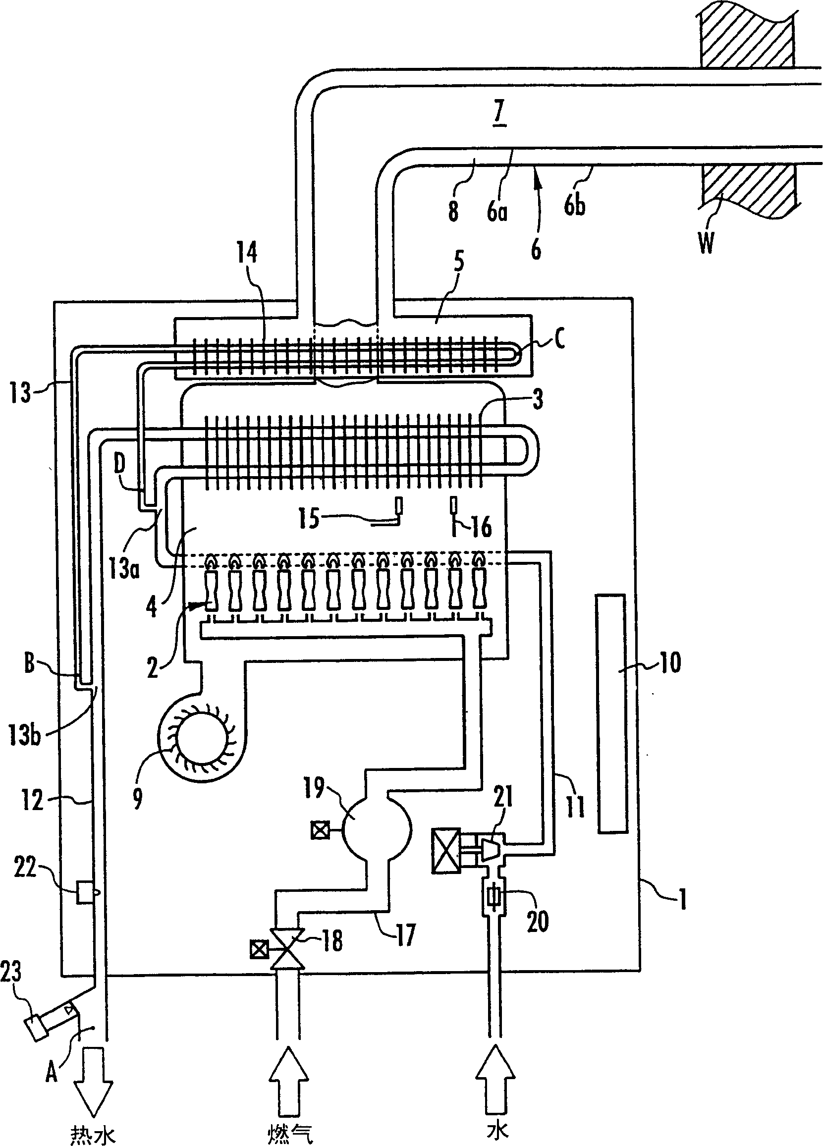
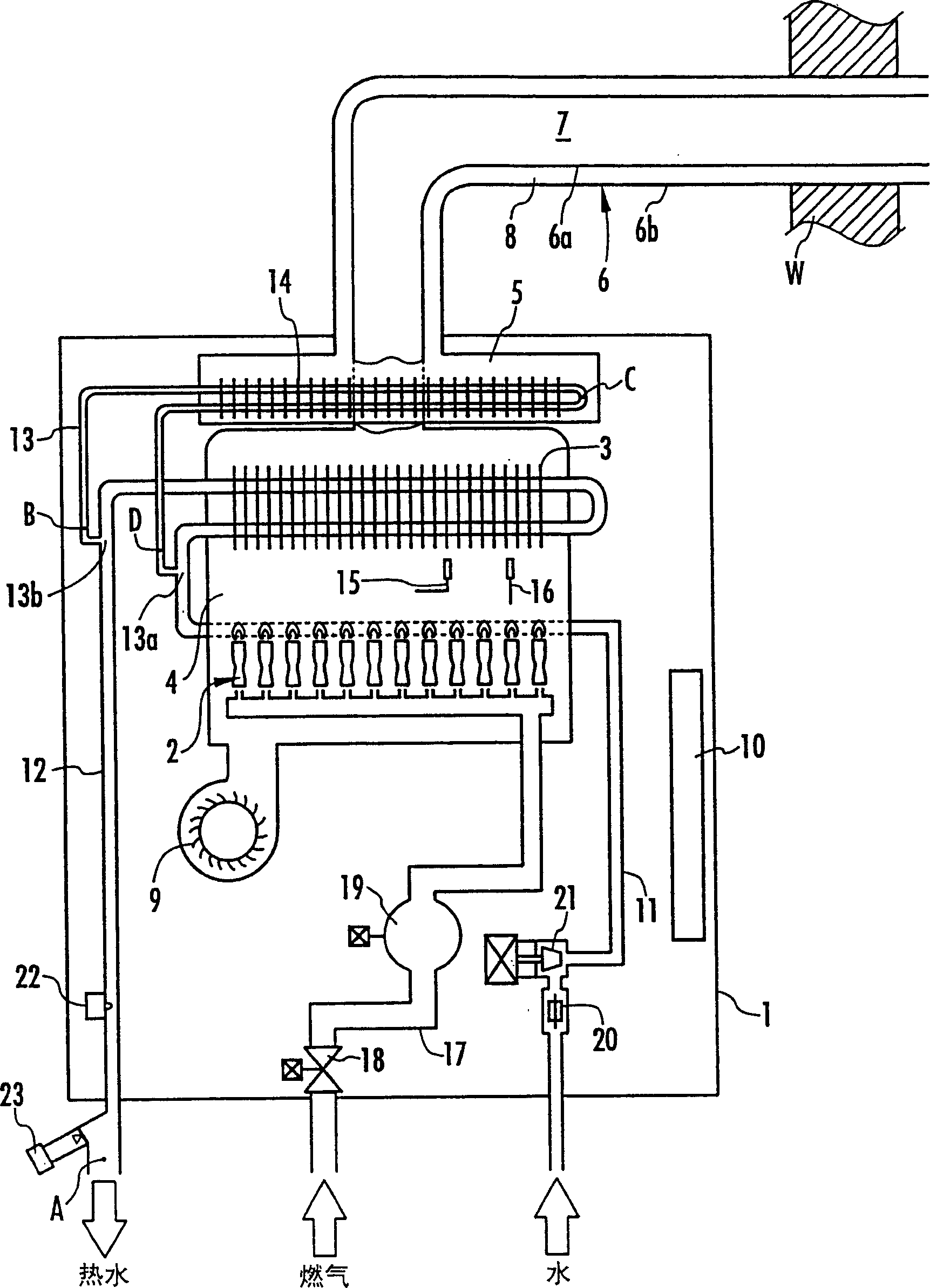
[0021] figure 1 The basic structure of the water heater of the embodiment shown, and image 3 In the water heater of the prior application shown, the same symbols as above are used for the same parts as the water heater of the prior application. Although it is a repetition of the description of the water heater of the prior application, only the structure of the water heater of this embodiment will be briefly described.

[0022] The water heater of this embodiment has a casing 1 and a combustion chamber 4 arranged in the casing 1 and having a substantially sealed structure. The burner 2 and the heat exchanger 3 for hot water supply heated by the burner 2 are housed in the combustion chamber 4 . Inside the housing 1 , an air supply chamber 5 that is located above the combustion chamber 4 and communicates with the inner space of the housing 1 is also disposed. In addition, t...


PUM


Abstract

A water heater, in which a housing (1) is provided above a combustion chamber (4) containing a burner (2) and a heat exchanger (3) for hot water supply and communicated with the air supply and exhaust. The air supply chamber (5) of the air supply path (8) of the pipe (6); the air is supplied to the combustion chamber as combustion air through the air supply path, the air supply chamber and the internal space of the housing through the combustion blower (9), And in the air supply chamber, a cooling heat exchanger (14) interposed on the bypass pipe (13) of the heat exchanger for hot water supply is arranged to cool the air flowing into the housing; At the time of stop, the high-temperature hot water boiled later by the hot water supply heat exchanger is transferred to the cooling heat exchanger to suppress the overheating of the outlet hot water temperature when the hot water is re-ejected. The confluence part (13b) of the bypass passage and the hot water outlet passage (12) is located at a vertically lower position relative to the branch part (13a) of the bypass passage and the water supply passage.

Description

technical field [0001] The present invention relates to a water heater having an air supply and exhaust pipe, and a combustion air blower is used to supply combustion air and discharge combustion exhaust through the air supply and exhaust pipe. Background technique [0002] As this water heater, the applicant has previously applied for such as image 3 The water heater shown is disclosed in Japanese Patent Application No. 2003-113734 (the application number in China is 03123727.4) bulletin. The water heater of this prior application has: a casing 1, a combustion chamber 4 arranged in the casing 1 and containing a burner 2 and a heat exchanger 3 for hot water supply heated by the burner 2, located in the The upper position of the combustion chamber 4 is disposed in the housing 1 and communicates with the air supply chamber 5 of the inner space of the housing 1, and communicates with the air supply chamber through the inner pipe 6a that communicates with the combustion chamber...

Claims


Application Information

Patent Timeline
IPC IPC(8): F24H1/10F24H1/14
Inventor 木村谦二永田真二
Owner RINNAI CORP
Why Eureka
Try Eureka