Liquid flow frame suitable for flow battery stack

A liquid flow battery and liquid flow frame technology, which is applied in fuel cells, fuel cell additives, regenerative fuel cells, etc., can solve problems such as uneven flow velocity distribution and weaken local thermal effects, so as to reduce local heat release and polarization , The effect of saving materials

Pending Publication Date: 2019-06-04
DALIAN INST OF CHEM PHYSICS CHINESE ACAD OF SCI +1
View PDF4 Cites 3 Cited by
  • Summary
  • Abstract
  • Description
  • Claims
  • Application Information

AI Technical Summary

Problems solved by technology

[0003] The purpose of the present invention is to propose and study a liquid flow battery suitable for flow battery stacks, aiming at the uneven flow velocity distribution of the electrolyte in the flow battery stack, especially in the flow battery stack. Frame, simple structure, convenient processing, through the scientific and reasonable design

Method used


Image

  • Liquid flow frame suitable for flow battery stack
  • Liquid flow frame suitable for flow battery stack
  • Liquid flow frame suitable for flow battery stack

Examples


Embodiment 1

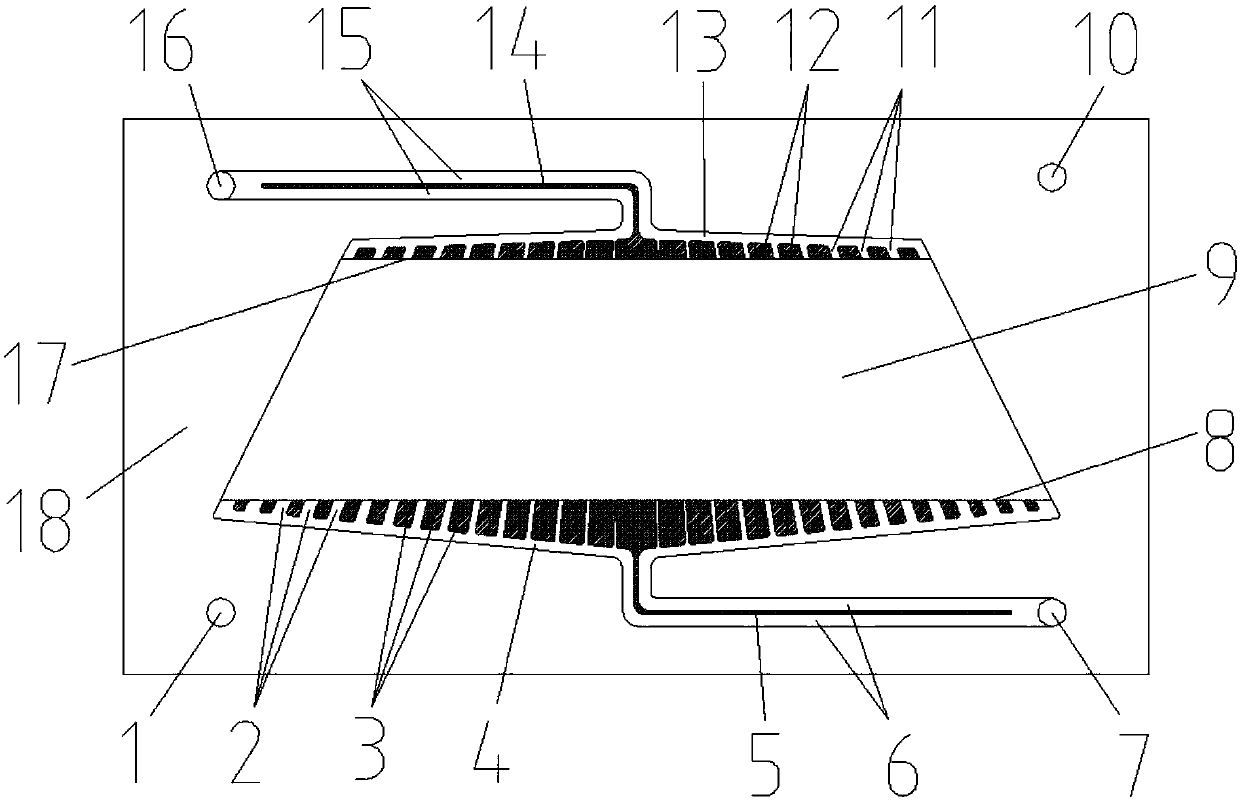
[0027] Such as figure 1As shown, a flow frame for a flow battery. It is made of polyethylene material and includes a liquid flow frame body 20. The frame body 20 is provided with a main flow inlet 7 of the positive electrolyte, a main flow inlet 1 of the negative electrolyte, a main flow outlet 16 of the positive electrolyte, and a main flow outlet 10 of the negative electrolyte. Wherein, the positive electrode electrolyte main flow inlet 7 and the negative electrode electrolyte main flow inlet 1 are located on the same side of the frame, the positive electrode electrolyte main flow outlet 16 and the negative electrode electrolyte main flow outlet 10 are located on the same side of the frame; the positive electrode electrolyte main flow inlet 7 and the positive electrode electrolyte The main flow outlet 16 is located on opposite sides of the frame body, and the main flow inlet 1 of the negative electrode electrolyte and the main flow outlet 10 of the negative electrode electro...

Embodiment 2

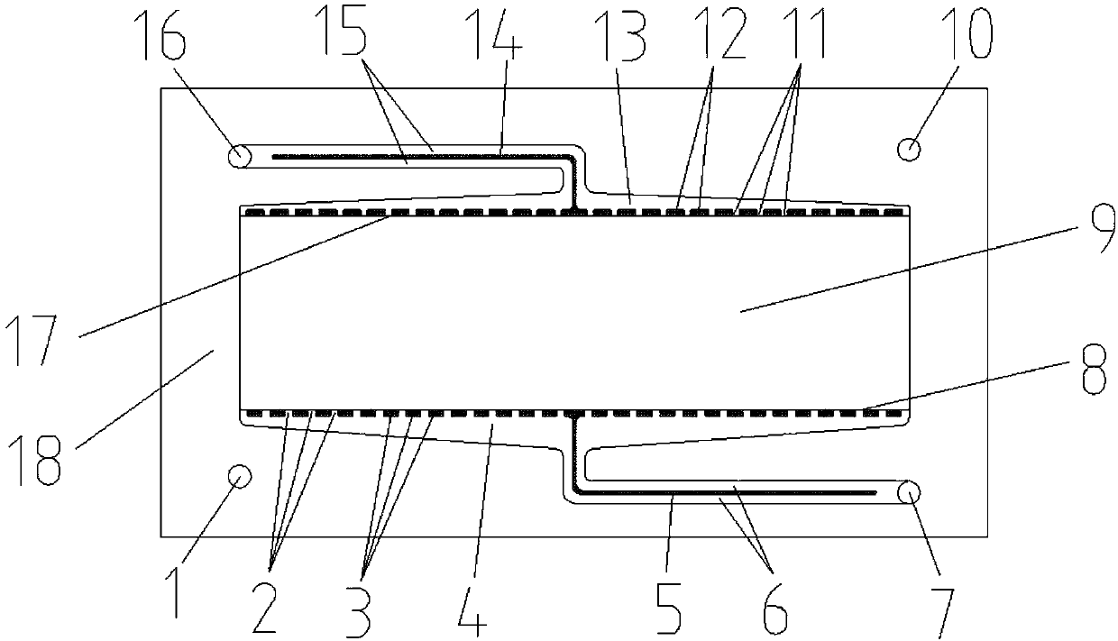
[0030] Such as figure 2 As shown, a flow frame for a flow battery. It is made of polyethylene material and includes a liquid flow frame body 20. The frame body 20 is provided with a main flow inlet 7 of the positive electrolyte, a main flow inlet 1 of the negative electrolyte, a main flow outlet 16 of the positive electrolyte, and a main flow outlet 10 of the negative electrolyte. Wherein, the positive electrode electrolyte main flow inlet 7 and the negative electrode electrolyte main flow inlet 1 are located on the same side of the frame, the positive electrode electrolyte main flow outlet 16 and the negative electrode electrolyte main flow outlet 10 are located on the same side of the frame; the positive electrode electrolyte main flow inlet 7 and the positive electrode electrolyte The main flow outlet 16 is located on opposite sides of the frame body, and the main flow inlet 1 of the negative electrode electrolyte and the main flow outlet 10 of the negative electrode elect...


PUM


Abstract

The invention relates to a liquid flow frame suitable for a flow battery stack or a flow battery. The liquid flow frame is a plate-shaped structure with through holes in the middle, the through holesare electrode regions, the cross sections of the through holes parallel to a plate body plane are rectangles or isosceles trapezoids, one side surface or two side surfaces of a plate are provided withgrooves for free flow areas of electrolyte close to edges of upper and lower bottom sides of the through holes, a groove at an edge of one side of the rectangle or a lower bottom side of the trapezoid is an inlet free flow area, an opposite side of the side of the rectangle or an upper bottom side of the trapezoid is an outlet free flow area, and more than two grooves for secondary flow guiding channels are set between each free flow area and the through holes. The liquid flow frame has the advantages of simple structure and convenient processing, the uniformity of electrolyte distribution can be effectively improved, the local overheating inside a reactor is suppressed, the polarization is reduced, and the electrolyte utilization is improved.

Description

technical field [0001] The invention relates to the field of flow batteries, in particular to a rectangular flow battery electrode frame. Background technique [0002] With the adjustment of the energy structure, the use of renewable energy such as wind energy and solar energy for power generation has attracted more and more attention. However, renewable energy power generation has the characteristics of discontinuity and instability, and it is difficult to directly connect to the grid. . Electric energy storage technology represented by liquid flow battery provides an opportunity to solve this problem. Electric propulsion is the core component of the flow battery, and its performance is directly related to the performance and cost of the entire system. The stack includes end plates, electrodes, liquid flow frames, ion exchange membranes and other components. Among them, the main function of the liquid flow frame is to ensure that the electrolyte flows into and out of the ...

Claims


Application Information

Patent Timeline
IPC IPC(8): H01M8/04186H01M8/04276H01M8/18
CPCY02E60/50
Inventor 郑琼张华民岳孟李先锋
Owner DALIAN INST OF CHEM PHYSICS CHINESE ACAD OF SCI
Why Eureka
Try Eureka