Relative position independently adjustable channel passband filter

A relative position, filter technology, applied in the direction of the filter, etc., can solve the problem of difficulty in independently adjusting the relative position of the channel, the coexistence of the channel and the passband, and the limitation of the application range of the channel bandpass filter.

Inactive Publication Date: 2005-06-22
TONGJI UNIV
View PDF0 Cites 7 Cited by
  • Summary
  • Abstract
  • Description
  • Claims
  • Application Information

AI Technical Summary

Problems solved by technology

[0009] The multi-channel bandpass filter based on the Fabry-Perot etalon and the heterojunction structure of the above-mentioned one-dimensional photonic crystal are difficult to indepen...

Method used


Image

  • Relative position independently adjustable channel passband filter
  • Relative position independently adjustable channel passband filter
  • Relative position independently adjustable channel passband filter

Examples


Embodiment Construction
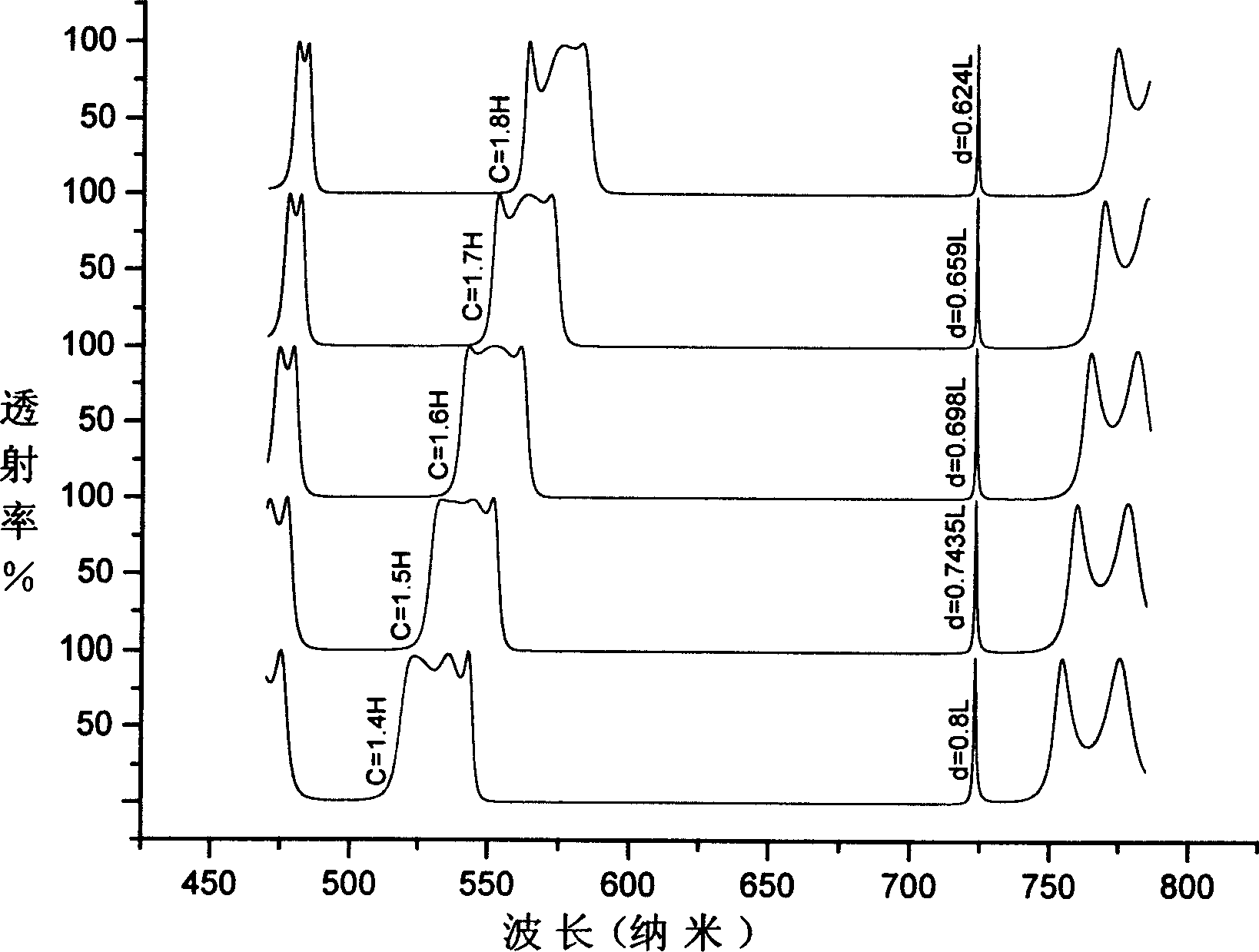
[0024] figure 2 The values ​​of c and d of several groups of figures shown are respectively c=1.4H, d=0.8L, c=1.5H, d=0.7435L, c=1.6H, d=0.698L, c=1.7H, d= 0.659L, c=1.8H, d=0.624L. As c is increased from 1.4 to 1.8 and d is properly adjusted, the position of the left passband gradually moves to the right, while the right channel remains unchanged at the original position.

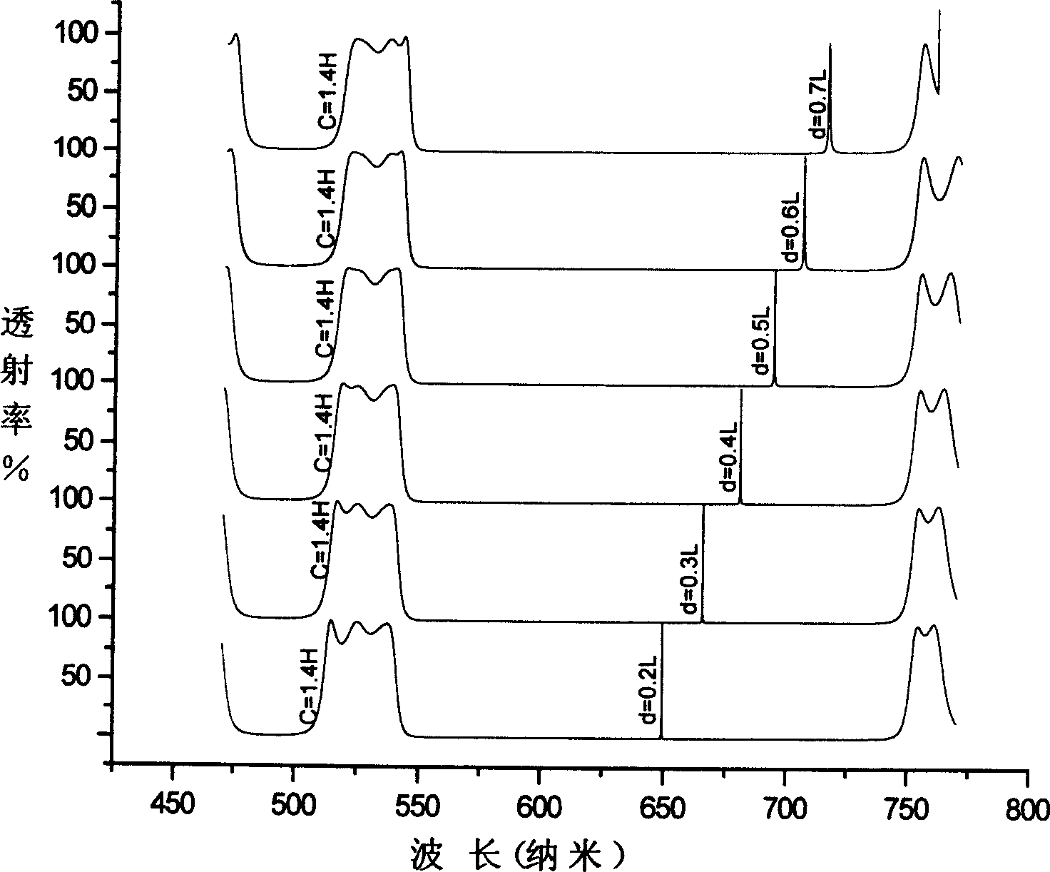
[0025] image 3 In the several groups of graphs shown, c=1.4H remains unchanged, and as the value of d increases from 0.2L to 0.7L, the position of the passband on the left remains basically unchanged. While the right channel moves gradually to the right.

[0026] Such as Figure 4 As shown, the values ​​of c and d corresponding to the passband spectral characteristic diagrams of these channels are c=1.5H, d=0.4L, c=1.5H, d=0.5L, c=1.6H, d=0.472L , c=1.6H, d=0.6L, c=1.7H, d=0.5677L, c=1.7H, d=0.7L, c=1.8H, d=0.662L, c=1.8H, d=0.8L , c=1.9H, d=0.755L, with different combinations of c and d, the posit...


PUM


Abstract

This invention provides a design method for independently regulating positions of channels and pass-bands in filters, which applies a symmetrical structure based on Fabry-Perot standard piece. Different from traditional narrow band filters and band-pass filters, it regulates positions of the channels and pass-bands by altering thickness of the middle layers to overcome position coherent phenomenon when adjusting the positions on the basis of coexistence. This invention introduces the design thinking and structure of the filter.

Description

technical field [0001] The invention relates to a design method of an optical filter device, in particular to a design of an optical filter with both channels and passbands. It has application prospects in optical instruments, astronomy, remote sensing, etc. Background technique [0002] Traditional multi-channel bandpass filters generally have the following two types: [0003] 1. Multi-channel bandpass filter based on Fabry-Perot etalon [0004] The most typical multi-channel bandpass filter is the Fabry-Perot etalon structure. The filter is a symmetrical structure, with reflective layers at both ends and a spacer layer in the middle. After multiple reflections of the reflective layer, by properly selecting the physical thickness of the spacer layer, this structure can obtain a bandpass with multi-channel transmission characteristics. filter, but since the positions of all channels are related to the thickness of this spacer layer, the position changes of these channels ...

Claims


Application Information

Patent Timeline
IPC IPC(8): G02B5/20
Inventor 吴永刚田国勋王占山林小燕
Owner TONGJI UNIV
Why Eureka
Try Eureka