
Positioning device of sliding rail

A positioning device and slide rail technology, applied in furniture parts, home utensils, drawers, etc., can solve problems such as unfavorable manual pressing, falling off or displacement, collision damage, etc.

Active Publication Date: 2005-06-29
KING SLIDE WORKS CO LTD
View PDF1 Cites 15 Cited by
  • Summary
  • Abstract
  • Description
  • Claims
  • Application Information

AI Technical Summary

Problems solved by technology

[0003] However, the positioning design of the above-mentioned slide rails to prevent the retraction of the middle rail, the movable plate is a movable assembly kit, which is easy to fall off or shift due to impact, and the movable plate is installed in the positioning piece, and the exposed part is very small, which can only be used for The push of the inner rail is not conducive to manual pressing, and this manual control requirement is mainly to prevent the drawer and the inner rail from being pulled out, and the extended middle rail will form a very long protrusion, which will hinder human activities. Or even cause collision damage, so it is necessary to manually release the anti-shrinkage positioning state of the middle rail, so as to put the middle rail into the outer rail, so as to avoid the inconvenience caused by the protrusion of the middle rail

Method used


Image

  • Positioning device of sliding rail
  • Positioning device of sliding rail
  • Positioning device of sliding rail

Examples


Embodiment Construction

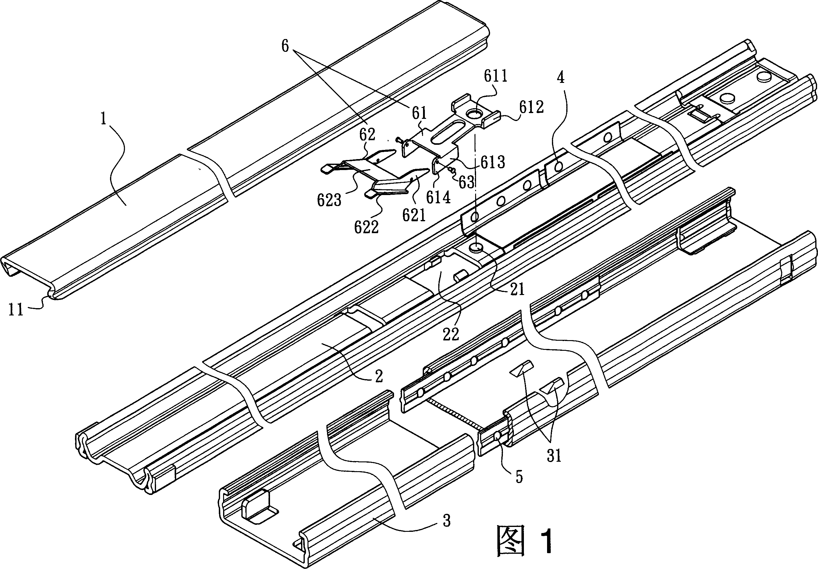
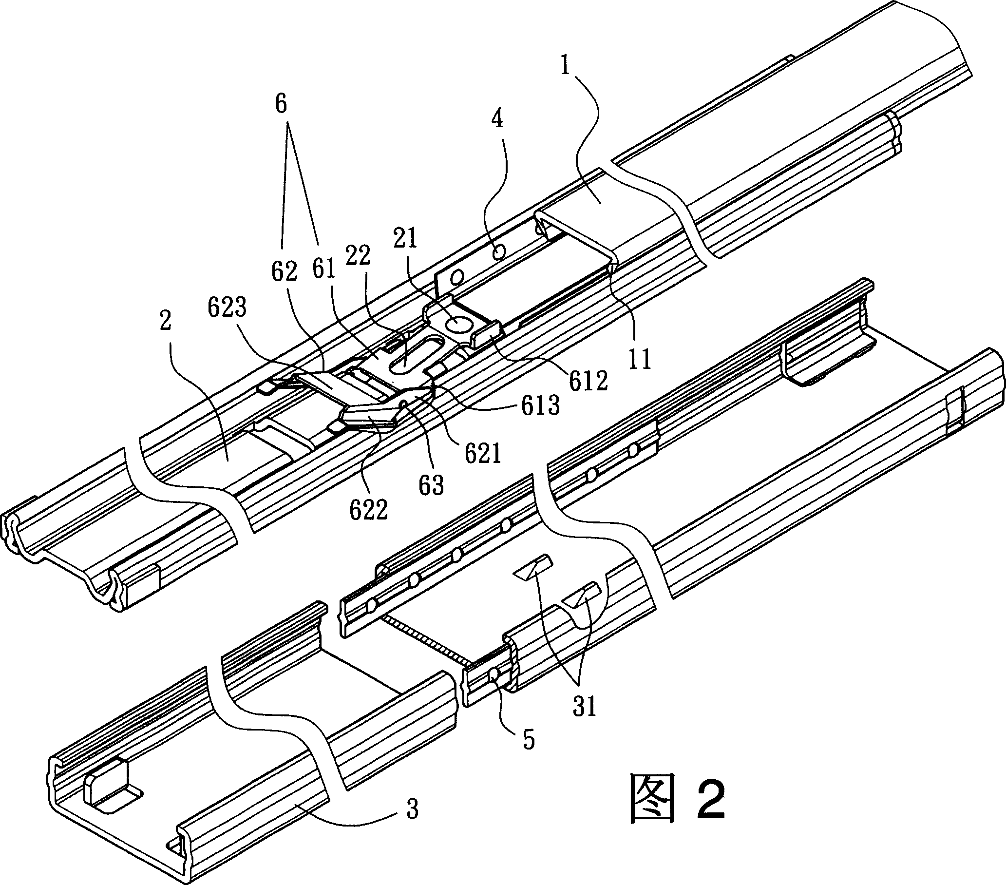
[0018] Referring first to Figures 1 and 2, the slide rail positioning device of the present invention can be used in a three-section slide rail to implement a basic structure that is the same as that of conventional products, and is between the inner rail 1 and the middle rail 2, and the middle rail 2 Between the outer rail 3 and the outer rail 3 are respectively provided sliding aids 4 and 5 to facilitate sliding, and the inner rail 1 and the middle rail 2, and the middle rail 2 and the outer rail 3 can relatively limit the pulling distance, but the pull-out stop The structure is not a feature of the present invention, so this part will not be illustrated and described in detail, and the partially disclosed structure in the accompanying drawings is not the only collocation structure of the present invention, and should not limit the protection scope of the invention patent of this application. The design structure of the present invention will be described in detail below.

...


PUM


Abstract

The invention provides a slide rail positioning device, which comprises a positioning set including a fixed sheet and an immobilizing sheet at the rear portion of the central rail, one end of the fixed sheet is mounted on the central rail, the central rail is provided with a hollow slot are for the fixed sheet to cross and extend to outside the outer rail surface, the fixed sheet is hinged with the immobilizing sheet on this side, forming a fastening portion on the lower margin, the outer rail is provided with a convex body, the immobilizing sheet is connected with the fixed sheet in a hinged mode by the two sides of extended hinged sheet, the other half is formed into buckled pressed portion, a pushing surface is formed between the two pressed portions, and the immobilizing sheet is supported on the central rail in a tilted position by the lower margin.

Description

(1) Technical field [0001] The invention relates to a slide rail positioning device. (2) Background technology [0002] For example, the steel ball slide rail used for the horizontal sliding of drawers is divided into two-section type and three-section type according to the number of telescopic sections. Since the development of this type of slide rail, there are quite a variety of mechanism designs that meet the functional requirements. Many patent requests have been filed, and the applicant has invested a lot of effort in this area. Among them, the design of the locking position of the related slide rail is a patented product like US Patent No. 6,585,335 "Locking structure of the rear section of the slide rail" , its main functional requirement is to enable the middle rail to be positioned after being pulled out relative to the outer rail, to prevent inward shrinkage, and to release the positioning state of the middle rail at the same time when the inner rail is retracted,...

Claims


Application Information

Patent Timeline
IPC IPC(8): A47B88/04
Inventor 陈庚金黄石龙王俊强
Owner KING SLIDE WORKS CO LTD
Learn More