Steel pipe cutting device

A technology for cutting devices and steel pipes, applied in the direction of pipe shearing devices, shearing devices, and accessories of shearing machines, etc., can solve the problems of poor positioning stability of steel pipes, inconvenient transportation of steel pipes, and low cutting efficiency, and achieve simple structure and improved cutting efficiency. Quality and cutting efficiency, the effect of low equipment cost

Inactive Publication Date: 2018-05-29
当涂县金龙凤科技股份有限公司
View PDF1 Cites 6 Cited by
  • Summary
  • Abstract
  • Description
  • Claims
  • Application Information

AI Technical Summary

Problems solved by technology

[0004] When the above-mentioned patents are cutting the steel pipe, the positioning stability of the steel pipe is poor and the...

Method used


Image

  • Steel pipe cutting device
  • Steel pipe cutting device
  • Steel pipe cutting device

Examples


Embodiment Construction

[0017] In order to make the technical means, creative features, goals and effects achieved by the present invention easy to understand, the present invention will be further described below in conjunction with specific embodiments.

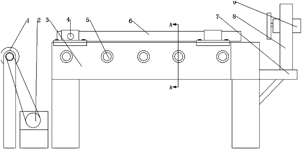
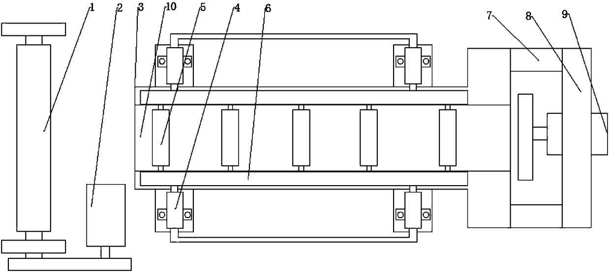
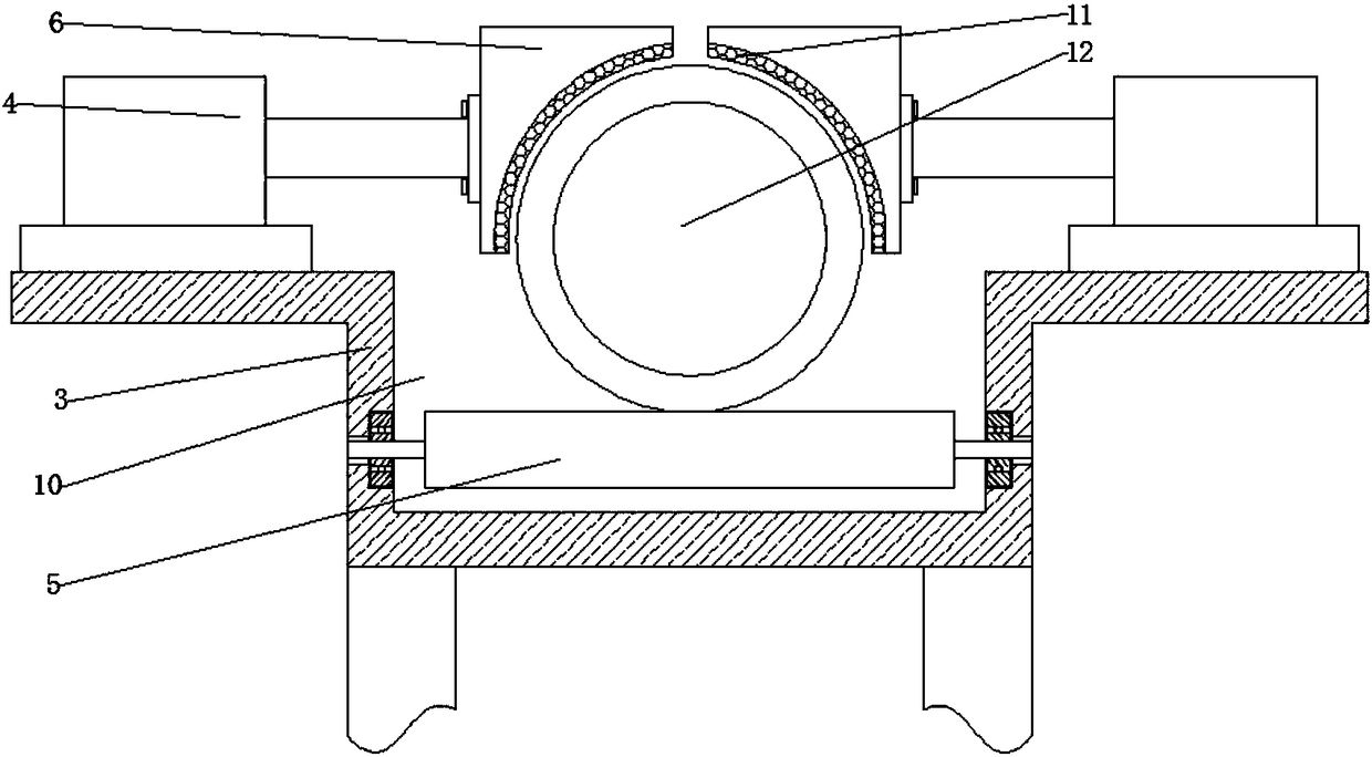
[0018] like Figure 1 to Figure 4 As shown, a steel pipe cutting device includes a support platform 3 and a cutting machine 9 positioned on one side of the support platform 3, the support platform 3 is supported on the ground by supporting feet, and the left side of the support platform 3 is provided with a driving idler 1 and a The driving motor 2, the driving roller 1 is supported on the ground by a bracket, the driving motor 2 is installed on the ground, the driving motor 2 is connected to the driving end of the driving roller 1 through a belt, and the supporting table 3 is provided with a U-shaped conveying Channel 10, in which a number of transmission rollers 5 distributed in parallel are installed, and the transmission rollers 5 and the driv...


PUM


Abstract

The invention discloses a steel pipe cutting device and relates to the technical field of mechanical equipment. The steel pipe cutting device comprises a supporting table and a cutting machine locatedon one side of the supporting table; the left side of the supporting table is provided with an active carrier roller and a driving motor; a conveying channel is formed in the supporting table and internally provided with a plurality of parallelly-distributed transmission rollers; two clamping mechanisms are symmetrically arranged on the two sides of the upper portion of the conveying channel andeach composed of a hydraulic cylinder and a pressing plate; the two clamping mechanisms are oppositely arranged, and a positioning groove for clamping a steel pipe is formed between the two clamping mechanisms; an extension section is arranged at the side end of the supporting table, and the hydraulic cylinders are mounted on the extension section in a fastened mode; and the back faces of the pressing plates are mounted at the telescopic ends of the hydraulic cylinders in a fastened mode, and the cutting machine is mounted on the right side of the supporting table through a supporting mechanism. The steel pipe cutting device is simple in structure and low in equipment cost, when the steel pipe is cut, the steel pipe can be effectively clamped, positioning is stable, and the cutting qualityand cutting efficiency of the steel pipe are improved.

Description

technical field [0001] The invention relates to the technical field of mechanical equipment, in particular to a steel pipe cutting device. Background technique: [0002] In steel pipe cutting, the steel pipe is often positioned by the positioning device first, and then the cutting machine is started to cut the steel pipe. The positioning device will not only affect the cutting efficiency of the steel pipe, but also have a certain impact on the cutting quality of the steel pipe. However, the existing positioning device has the defects of complex structure and poor positioning effect. [0003] The Chinese patent application number 201420189004.4 discloses a positioning device for steel pipe cutting, including: a cutting table, a first positioning device and a second positioning device, the first positioning device and the second positioning device are arranged on the cutting table in parallel, And it can freely slide in the guide mechanism on the side of the cutting table; th...

Claims


Application Information

Patent Timeline
IPC IPC(8): B23D21/00B23D33/04
CPCB23D21/00B23D33/04
Inventor 张万宝
Owner 当涂县金龙凤科技股份有限公司
Why Eureka
Try Eureka