Light deflector and rear-projection screen

一种光偏转器、背面的技术,应用在仪器、光学、漫射元件等方向,能够解决图像鲜明度受损、光损失、双凸透镜片散射特性困难等问题,达到提高利用效率的效果

Inactive Publication Date: 2005-07-13
MITSUBISHI ELECTRIC CORP
View PDF5 Cites 3 Cited by
  • Summary
  • Abstract
  • Description
  • Claims
  • Application Information

AI Technical Summary

Problems solved by technology

Therefore, there is a problem that the sharpness of the image is impaired due to the occurrence of ghosting and stray light due to the aforementioned reflected light, and the projected image becomes dark.
However, since the shape of the reflective prism that can be used is limited in order to prevent the aforementioned light from returning to the incident surface side, it is difficult to obtain the scattering characteristics required for the lenticular lens sheet.
[0022] In addition, in order to reduce ghosting, when a curtain-shaped light-absorbing sheet is used, there is a problem that light loss occurs due to the influence of the thickness of the light-absorbing sheet, and the entire screen becomes dark.

Method used


Image

  • Light deflector and rear-projection screen
  • Light deflector and rear-projection screen
  • Light deflector and rear-projection screen

Examples


Embodiment approach 1

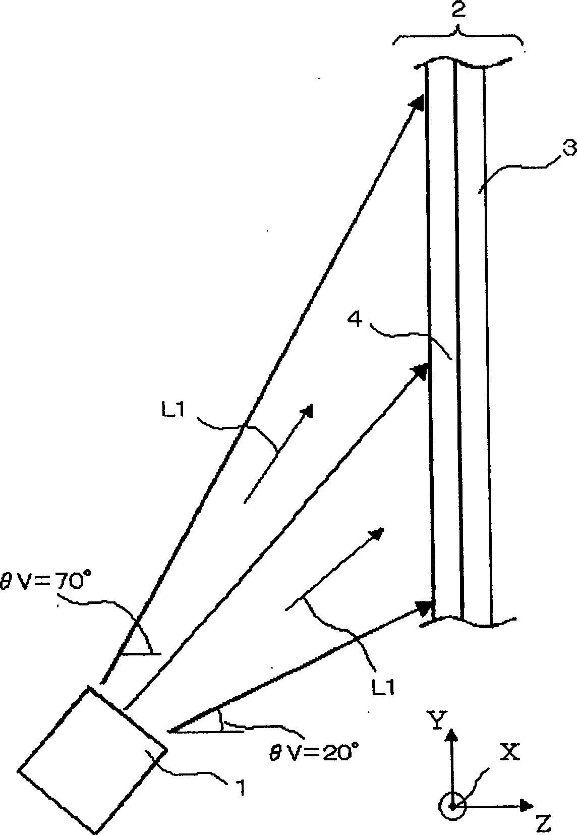
[0044] figure 1 It is a side view of the rear projection screen 2 in Embodiment 1. exist figure 1 Among them, the light projected from the light projection unit 1 (hereinafter referred to as projected light) is along the traveling direction of the light ( figure 1 While the L1) in is diffusing, it travels toward the rear projection screen 2. In this way, the image projected by the aforementioned light projection unit 1 is enlarged and projected onto the rear projection screen 2 . The rear projection screen 2 is composed of a light deflector 4 and a lenticular lens sheet 3 , and the light projected from the light projection unit 1 is first incident on the light deflector 4 . In addition, in the following description, the light incident on components such as the light deflector 4 and the lenticular lens sheet 3 constituting the rear projection screen 2 is called incident light, and the light emitted from the components is called outgoing light. In addition, the surface on wh...

Embodiment approach 2

[0074] Figure 6 It is a side view of the rear projection screen 22 in Embodiment 2. exist Figure 6 Among them, the projection light projected from the light projection unit 1 is along the traveling direction of the light ( Figure 6 L1) in ) diffuses and travels to the rear projection screen 22. In addition, in this embodiment, the same reference numerals are attached to the same configurations as those described in Embodiment 1 above, and description thereof will be omitted.

[0075] The rear projection screen 22 in Embodiment 2 is configured by bringing the first lens sheet 5 and the second lens sheet 6 close together and holding them with a projection screen holding frame (not shown) or the like.

[0076] The light projected from the light projection unit 1 first enters the second lens sheet 6 . The rear projection screen 22 imparts uniform directivity over the entire screen to the projection light projected from the light projection unit 1 onto the rear projection sc...

Embodiment approach 3

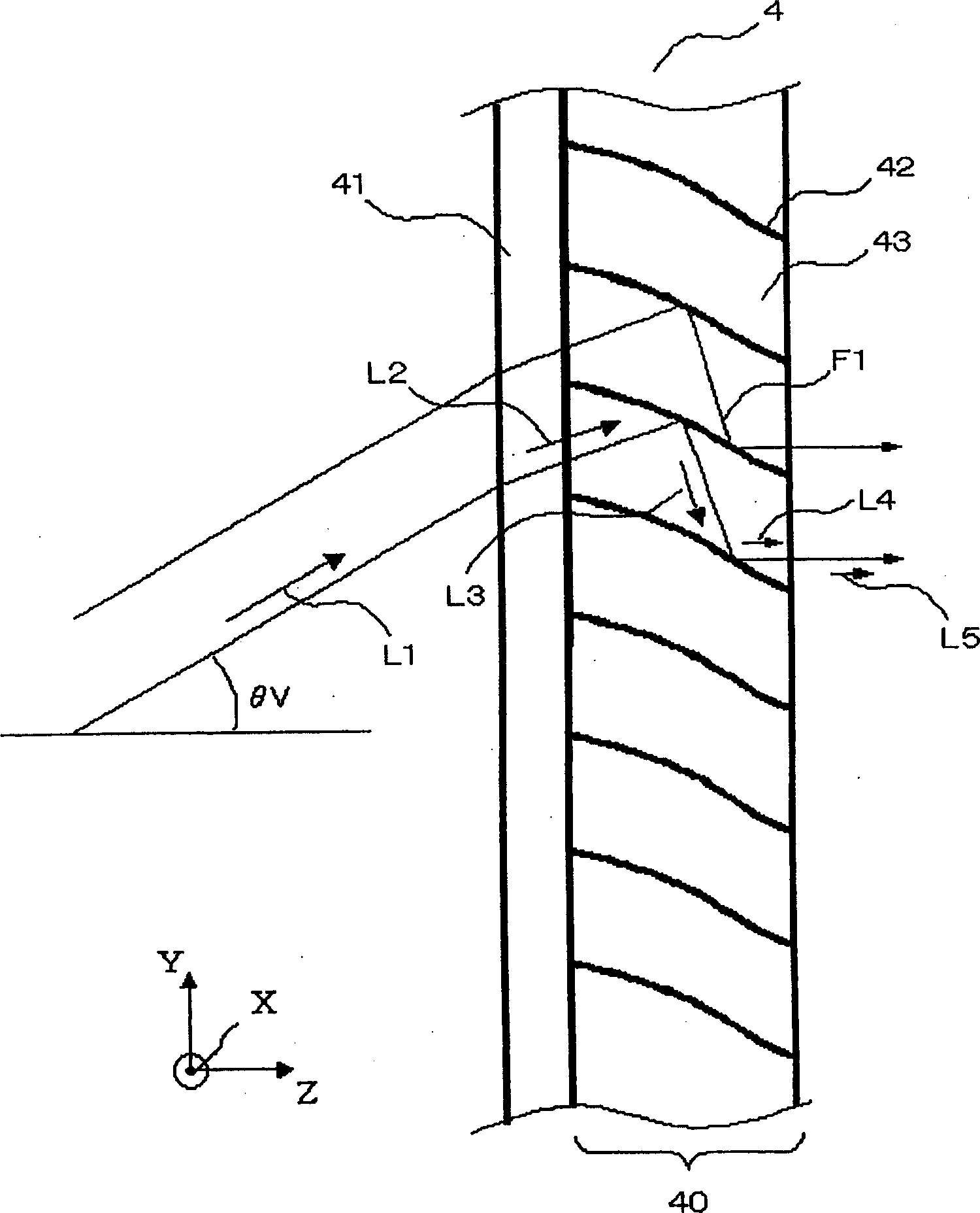
[0104] Figure 10 It is a side view of the case where the rear projection screen 23 in Embodiment 3 was seen from the X-axis direction. In this figure, the projection light projected from the light projection unit 1 travels to the rear projection screen 23 while being diffused along the traveling direction L1 of the light. Then, the aforementioned projection light reaches the rear projection screen 23 , so that the image projected by the aforementioned light projection unit 1 is enlarged and projected onto the rear projection screen 23 . The rear projection screen 23 in this embodiment is configured such that the first lens sheet 7 , the second lens sheet 8 , and the Fresnel lens sheet 9 are brought close to each other and integrally held. In addition, the aforementioned Fresnel lens sheet 9 is a lens sheet having a light-gathering ability of 0 (zero), and is provided on the incident surface of the rear projection screen 23 .

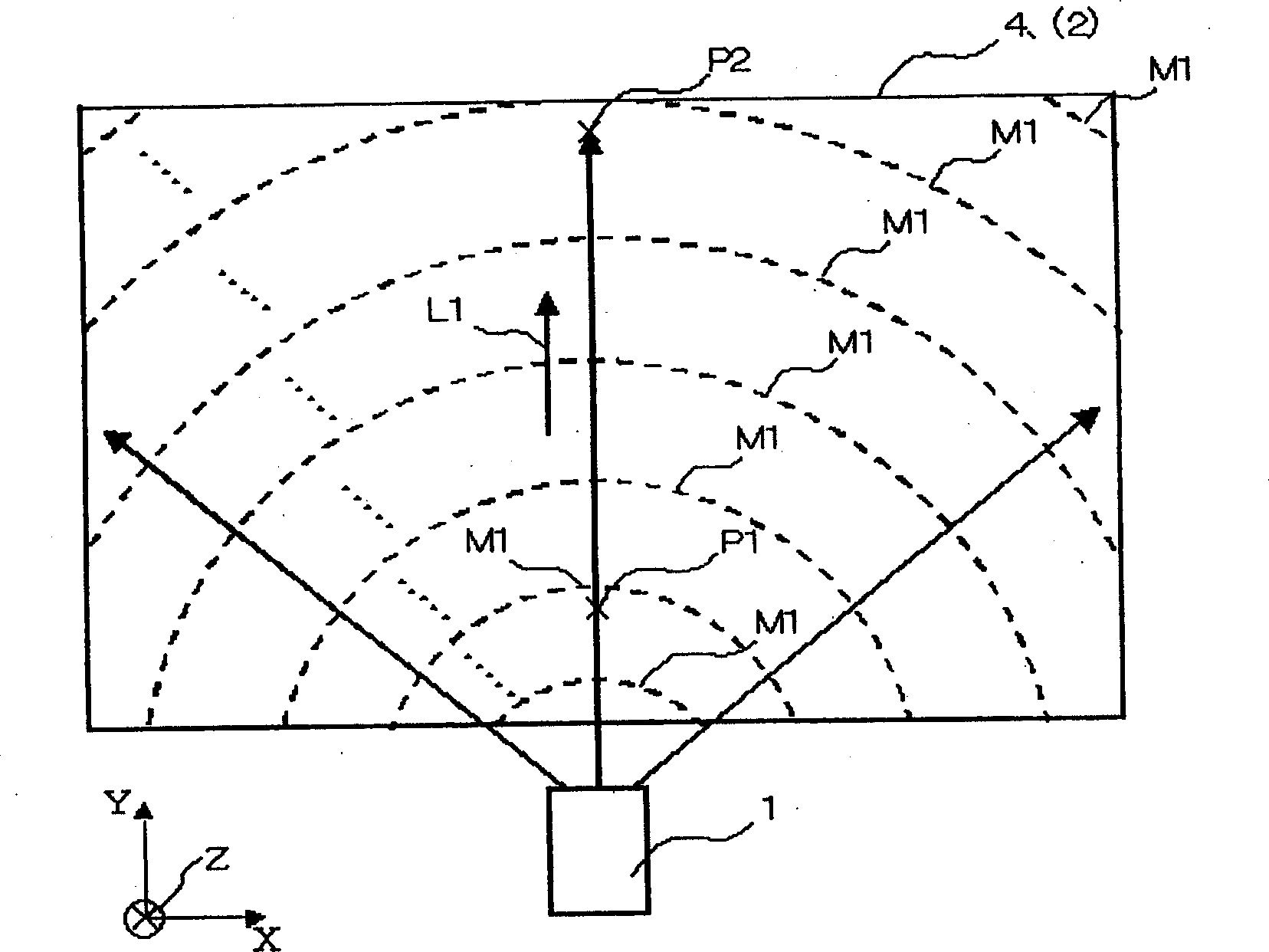
[0105] Figure 11 It is an explanatory diagram...


PUM

PropertyMeasurementUnit
refractive indexaaaaaaaaaa

Abstract

The present invention provides a light deflector and a back projection screen, to obtain a back projection screen that can be achieved by improving the utilization efficiency of light throughout the screen, suppressing the effects of ghosting and stray light, and obtaining a vivid image within the entire frame. It is characterized in that there are multiple reflective units disposed side by side in a specified direction, the reflective unit having: the 1st reflective surface, set on the incident side of the light, reflecting the aforementioned light so that it concentrates; and the 2nd reflective surface, which is set on the outlet side of the aforementioned light, and reflects the aforementioned light reflected by the aforementioned 1st reflector; The light reflected by the aforementioned 1 reflective surface in a plurality of the preceding reflective units in the 1 reflective unit is reflected by the aforementioned 2nd reflective surface adjacent to the 1 reflective unit.

Description

technical field [0001] The present invention relates to a light deflector and a rear projection screen for correcting the direction of travel of light projected from the rear. Background technique [0002] [Patent Document 1] [0003] Japanese Patent Laid-Open No. 2002-196422 (Page 6, Figure 2) [0004] [Patent Document 2] [0005] Japanese Patent Laid-Open Publication No. 7-64189 (page 11, figure 2) [0006] [Patent Document 3] [0007] Japanese Patent Laid-Open No. 61-52601 (Page 5, Figure 4) [0008] [Patent Document 4] [0009] Japanese Patent Laid-Open No. 2002-311211 (Page 9, Figure 3) [0010] [Patent Document 5] [0011] US Patent No. 5254388 (Sheet 1 of 2, Fig.1) [0012] The conventional rear projection screen passes the incident surface of the Fresnel lens sheet provided with circular Fresnel lenses and the lenticular lens sheet provided with cylindrical lenses linearly along the vertical direction (the vertical direction of the screen). The faces face ea...

Claims


Application Information

Patent Timeline
Patent Type & Authority Applications(China)
IPC IPC(8): F21S11/00F21V11/06G02B5/02G02B5/08G02B5/09G03B21/62
CPCF21S11/00F21V11/06G03B21/62
Inventor 日比武利中野勇三
Owner MITSUBISHI ELECTRIC CORP
Why Eureka
Try Eureka